Fixture for milling axially-overlapped thin-wall disc type workpieces

An axial overlap and fixture technology, applied in the direction of manufacturing tools, metal processing machinery parts, clamping, etc., can solve the problems of long time for tightening the platen screws, difficulty in ensuring processing requirements, and inability to uniform pressure, achieving simple structure, The effect of low manufacturing cost and improved processing efficiency

Pending Publication Date: 2021-12-31
CHINA ELECTRONIC TECH GRP CORP NO 38 RES INST
View PDF10 Cites 0 Cited by
  • Summary
  • Abstract
  • Description
  • Claims
  • Application Information

AI Technical Summary

Problems solved by technology

Its disadvantages are: the clamping is more cumbersome, and it takes a long time to tighten the pressure plate screws; when processing the end face, it is difficult to meet the processing requirements because the sheet is too thin; no matter how many pressure plates are added around the part, it is impossible to obtain uniformity at every point around the part. If each clamping point around it cannot obtain uniform pressure, that is, pressing force, the cutting force will be concentrated on several clamping points during cutting, resulting in deformation of the part after processing, resulting in the scrapping of the part

Method used


Image

  • Fixture for milling axially-overlapped thin-wall disc type workpieces
  • Fixture for milling axially-overlapped thin-wall disc type workpieces
  • Fixture for milling axially-overlapped thin-wall disc type workpieces

Examples


Embodiment 1

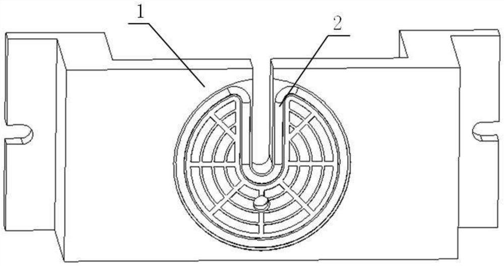
[0020] Such as figure 1 as shown, figure 1 It is a structural view of the jig for milling thin-walled disc workpieces with overlapping axial distribution;

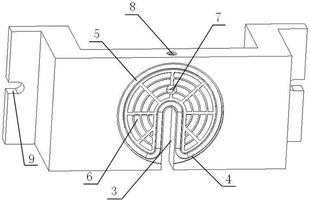
[0021] Such as figure 2 as shown, figure 2 It is a structural view of the fixture main body; the fixture main body 1 includes a workbench and pillars symmetrically arranged on both sides of the workbench, and the space formed in the middle is used to avoid the rest of the parts that are not clamped. A notch 9 for clamping and fixing is provided on the pillar, a circular positioning groove 4 and an opening groove 3 are arranged on the worktable, the circular positioning groove 4 is formed by sinking the end face of the worktable, and The diameter of the circular positioning groove 4 is set in cooperation with the diameter of the thin-walled disc workpiece for accurate positioning of the thin-walled disc workpiece.

[0022] The opening groove 3 extends linearly from the center of the circular positioning groove 4 to th...

Embodiment 2

[0030] Such as Figure 4 as shown, Figure 4 It is a schematic diagram of the use of the fixture for milling thin-walled disc workpieces with overlapping axial distribution; during processing, the connection joint 10 of the vacuum pump is connected to the threaded hole 8, and the fixture main body 1 is fixed through the gap 9, The part 11 is clamped on the fixture main body 1 through the opening groove 5, and the disc to be processed of the part 11 is fixed on the circular positioning groove 4, and the vacuum pump valve is opened, and gently pressed by hand It is determined whether the disc to be processed of the part 11 is clamped flat, so as to complete the whole process of positioning and clamping of the quick clamp.


PUM


Abstract

The invention discloses a fixture for milling axially-overlapped thin-wall disc type workpieces. The fixture comprises a fixture main body and an annular sealing strip, the fixture main body comprises a working table plate, a circular positioning groove and an open groove are formed in the working table plate, the end face of the working table plate sinks to form the circular positioning groove, the open groove linearly extends from the circle center of the circular positioning groove to the edge of the circular positioning groove, the open groove penetrates through the working table plate in the thickness direction of the working table plate, and a sealing groove used for containing the annular sealing strip is formed in the circular positioning groove. The fixture is simple in structure, safe and reliable; for the characteristic of poor rigidity of the thin workpieces, flat, solid and reliable clamping is realized, and the design requirements of axial size precision and the like of the workpieces are effectively ensured; and the thin ring workpieces can be rapidly installed, the machining efficiency is improved, and the beneficial effects of being low in manufacturing cost and the like are achieved.

Description

technical field [0001] The invention relates to the technical field of clamping and positioning for milling, in particular to a clamp for milling thin-walled disk-like workpieces with overlapping distribution in the axial direction. Background technique [0002] In the process of CNC milling, thin-walled disc parts are relatively common processing types. However, for some thin-walled disc parts, the thin-walled discs are overlapped in the axial direction. When milling such parts, a platform form is often used, and a pressure plate is added around to fix it. Its disadvantages are: the clamping is more cumbersome, and it takes a long time to tighten the pressure plate screws; when processing the end face, it is difficult to meet the processing requirements because the sheet is too thin; no matter how many pressure plates are added around the part, it is impossible to obtain uniformity at every point around the part. If each clamping point around it cannot obtain uniform pres...

Claims


Application Information

Patent Timeline
Patent Type & Authority Applications(China)
IPC IPC(8): B23Q3/06B23Q3/08
CPCB23Q3/065B23Q3/088
Inventor 张玲丽汪章洪王建中王平徐西姚凯
Owner CHINA ELECTRONIC TECH GRP CORP NO 38 RES INST
Why Eureka
Try Eureka