
Impact test machine with steel ball self-reset function

A test test, self-homing technology, applied in the direction of impact test, machine/structural component test, measurement device, etc., can solve the problems of low efficiency, increased labor intensity, long test process, etc. Effect

Inactive Publication Date: 2016-02-03
KUSN MINGJIU ELECTROMECHANICAL
View PDF10 Cites 2 Cited by
  • Summary
  • Abstract
  • Description
  • Claims
  • Application Information

AI Technical Summary

Problems solved by technology

Since the test test often has to pass multiple tests, the steel ball must be picked up manually for each test, which increases labor intensity and inefficiency, making the test process lengthy

Method used


Image

  • Impact test machine with steel ball self-reset function
  • Impact test machine with steel ball self-reset function
  • Impact test machine with steel ball self-reset function

Examples


Embodiment 1

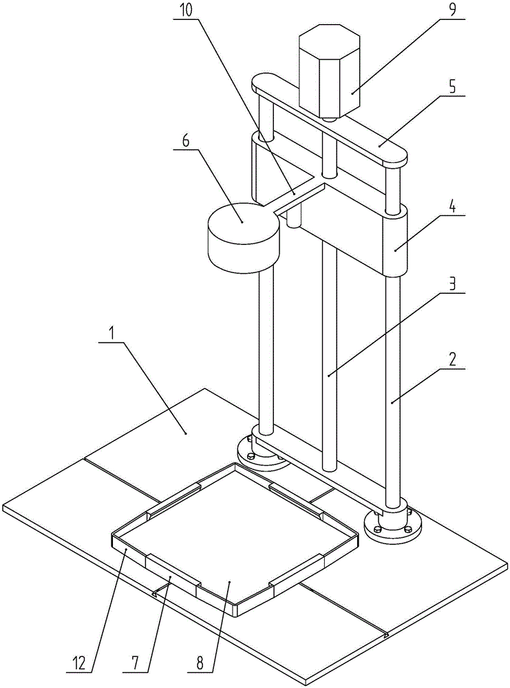
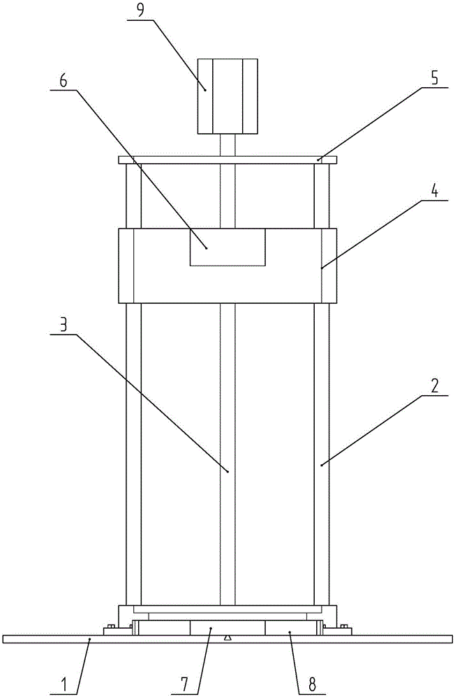
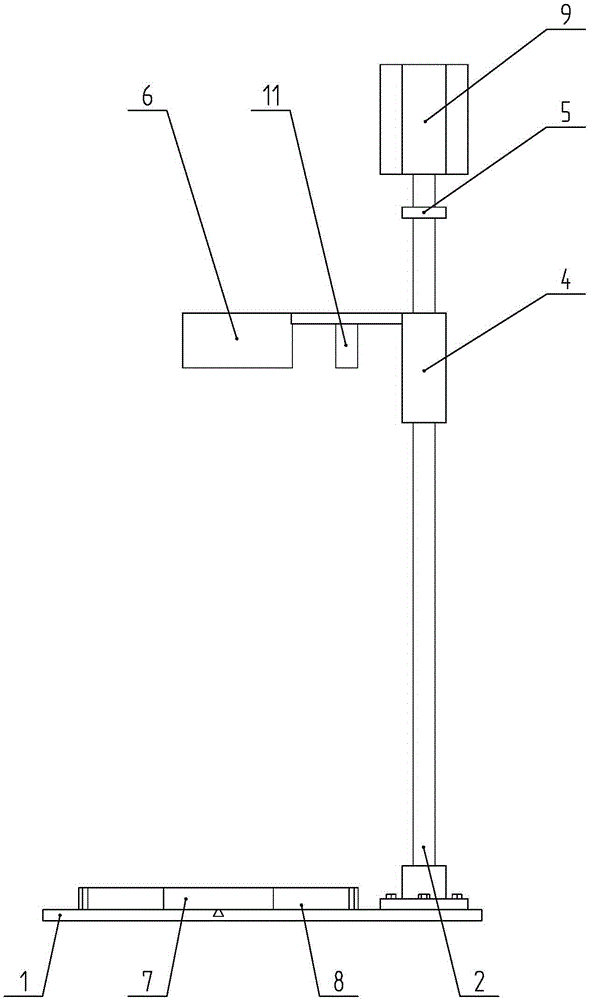
[0022] like Figures 1 to 4 As shown, a steel ball self-returning impact resistance testing machine includes a test stand 1 and a test stand installed on the test stand 1. The test frame includes a lead screw 3, two guide columns 2, a slide table 4, a beam 5, and a motor 9. Lead screw and guide post 2 are all vertically installed on the test bench 1, and lead screw 3 is positioned at the center of two guide posts 2, and lead screw 3 can rotate, and guide post 2 is fixed. A crossbeam 5 for fixing the motor 9 is installed on the tops of the two guide posts 2 , and the upper end of the leading screw 3 is connected with the main shaft of the motor 9 . The slide table 4 cooperates with the lead screw 3 through the screw pair, and cooperates with the guide post 2 through the moving pair. A horizontal support 10 is installed on the slide table 4, and a downward magnetic base 6 and a laser range finder 11 are installed on the support 10; the bottom end surface of the magnetic base 6...

Embodiment 2

[0026] In the present invention, the positioning block 7 includes a vertical portion and a horizontal portion connected to the vertical upper end, and the side for positioning on the positioning block 7 is the inner side of the aforementioned two.

[0027] Working process and principle of the present invention

[0028] Place the object under test on the test table, and place the positioning block in contact with each edge of the object under test, pull the elastic band to make it clamp the edge of the main object under test and then achieve pre-positioning under the action of tightening force, and then Secure by tightening bolts. Determine the test height H and select the steel ball according to the test requirements, then start the motor 9 to control the sliding table 4 to descend until the bottom surface of the magnetic base 6 is in contact with the steel ball, and then pause. At this time the height is H 1 (ie steel ball diameter D). Then start motor 9 to control slide t...


PUM


Abstract

The invention discloses an impact test machine with a steel ball self-reset function, comprising a test bench. The test machine is characterized in that two pairs of positioning blocks are mounted on the test bench in a sliding manner, and the two pairs of positioning blocks surround a square area; one pair of positioning blocks can move transversely on the test bench, and the other pair of positioning blocks can move longitudinally on the test bench; and the ends of two adjacent positioning blocks are connected by an elastic band. The beneficial effect of the invention is as follows: the elastic bands can provide a certain pre-tightening force to pre-position a tested object, and the elastic bands and the positioning blocks can form an area for limiting the rolling range of a steel ball, so that the magnetic force of a magnetic base can attract the steel ball to a specified position, there is no need to pick steel ball back manually, and time and labor are saved. The positioning blocks can both limit the movement of the tested object in the horizontal direction and limit the movement of the tested object in the vertical direction. Thus, fixation is firmer, and test is facilitated.

Description

technical field [0001] The invention belongs to the technical field of testing equipment, and in particular relates to a steel ball self-returning impact resistance testing machine. Background technique [0002] Electronic devices with screens, such as notebook computers, tablet computers, mobile communication terminals, liquid crystal screens, etc., need to test the impact resistance of the finished products to be tested when they are made or assembled. [0003] At present, the test process of the impact resistance test is to absorb the steel ball through the magnetic seat and rise it to the test height, and then make it fall freely to the surface of the measured object. One disadvantage of this test method is that the steel ball will roll to a far position after falling, and it must be picked up manually and placed under the magnetic base for the next test. Since the test often needs to pass through multiple sets of tests, the steel balls must be picked up manually for ea...

Claims


Application Information

Patent Timeline
Patent Type & Authority Applications(China)
IPC IPC(8): G01M7/08
Inventor 张月霞
Owner KUSN MINGJIU ELECTROMECHANICAL
Learn More