Calibration method for electromagnetic compatibility test system

A technology of electromagnetic compatibility and testing system, applied in the direction of measuring devices, measuring electrical variables, instruments, etc., can solve problems such as difficulty in providing demand voltage, and achieve the effect of improving the method of measuring and determining the level and ensuring the accuracy

Active Publication Date: 2016-02-03
LUOYANG INST OF ELECTRO OPTICAL EQUIP OF AVIC
View PDF4 Cites 6 Cited by
  • Summary
  • Abstract
  • Description
  • Claims
  • Application Information

AI Technical Summary

Problems solved by technology

[0006] The purpose of the present invention is to provide a calibration method for an electromagnetic compatibility test system, in order to solv...

Method used


Image

  • Calibration method for electromagnetic compatibility test system
  • Calibration method for electromagnetic compatibility test system
  • Calibration method for electromagnetic compatibility test system

Examples


Embodiment Construction

[0023] The present invention will be described in further detail below in conjunction with the accompanying drawings.

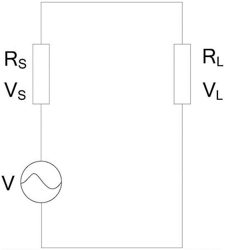
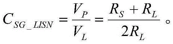
[0024] Such as figure 2 Shown is the internal circuit diagram of the signal generator in the present invention, that is, the voltage division diagram of the signal generator. exist figure 2 , Rs and R L are the impedances of the signal generator and LISN, respectively, V S and V L are the voltages at both ends of the signal generator and LISN, V represents the total output voltage of the signal generator, V P is the nominal output voltage of the signal generator. Since it is required that the level indicated by the data recording device should be within the range of ±3dB of the injection level, the combination figure 2 The voltage divider circuit diagram can get the calculation formula of the nominal output voltage of the signal generator,

[0025] V p = 0.5 × V ...


PUM


Abstract

The invention relates to a calibration method for an electromagnetic compatibility test system. The calibration method comprises the steps: 1) determining the LISN impedance and the output voltage VL of the LISN in a signal-generator bleeder circuit according to the input frequency of an electromagnetic compatibility test system; 2) determining the input correction factor CSG_LISN of the LISN according to the relevant standard in the electromagnetic compatibility test and the voltage division relation between the signal-generator impedance and the LISN impedance in the signal-generator bleeder circuit; and 3) calculating the nominal output voltage VP of the signal-generator according to the output voltage VL of the LISN determined in the step 1) and the input correction factor CSG_LISN calculated in the step 2). By means of the LISN factor concept provided by the calibration method for an electromagnetic compatibility test system, the nominal output level of the signal-generator can be quickly and accurately determined through definition and application of the LISN factor so that the input end of the LISN can achieve the expectant target level.

Description

technical field [0001] The invention relates to the technical field of electromagnetic compatibility testing, in particular to a calibration method for an electromagnetic compatibility testing system. Background technique [0002] As the battlefield environment and the internal electromagnetic environment of the weapon itself become more and more complex, weapons and equipment have requirements for their electromagnetic compatibility and are tested and assessed. The current military standards used in the electromagnetic compatibility testing of weapons and equipment in my country are GJB151A-97: "Requirements for Electromagnetic Emission and Sensitivity of Military Equipment and Subsystems" and GJB152A-97: "Measurement of Electromagnetic Emission and Sensitivity of Military Equipment and Subsystems". The two standards stipulate the electromagnetic emission (EMI) and electromagnetic susceptibility (EMS) tests of our country's military products. GJB151A-97 stipulates a total o...

Claims


Application Information

Patent Timeline
IPC IPC(8): G01R35/00
Inventor 孙晋王伯生张佳
Owner LUOYANG INST OF ELECTRO OPTICAL EQUIP OF AVIC
Why Eureka
Try Eureka