
Optical computer based on control of smart phone

A smart phone and optical computer technology, applied in the field of optical projection computer, can solve the problem that the optical projection area cannot be input

Inactive Publication Date: 2016-02-03
INTELLIGENCE YOCHU GUANGZHOU TECH CO LTD
View PDF4 Cites 3 Cited by
  • Summary
  • Abstract
  • Description
  • Claims
  • Application Information

AI Technical Summary

Problems solved by technology

However, the light projection area needs to have a projection plane, such as a table, coffee table, tablet, etc. In the absence of a projection plane, such as the beach, knees, handheld and other environments, the light projection area cannot be input

Method used


Image

  • Optical computer based on control of smart phone
  • Optical computer based on control of smart phone
  • Optical computer based on control of smart phone

Examples


Embodiment Construction

[0011] The present invention will be described in further detail below with specific embodiments in conjunction with the accompanying drawings.

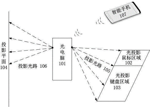
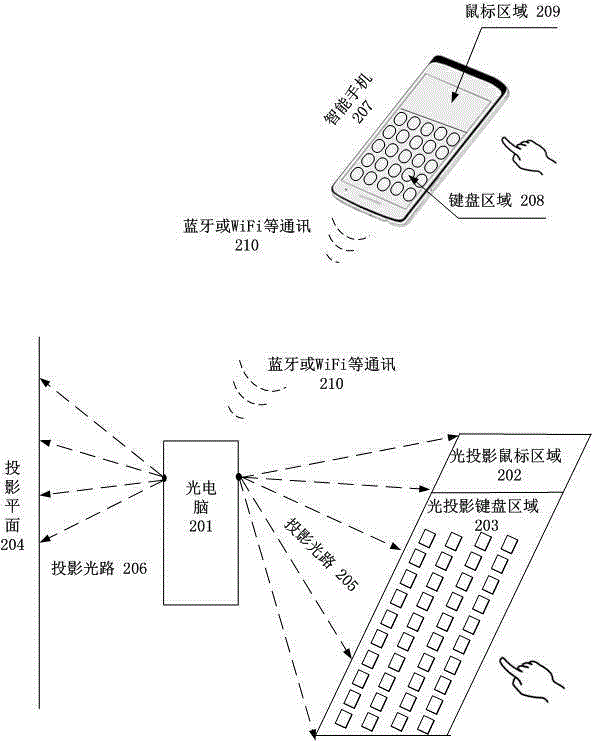
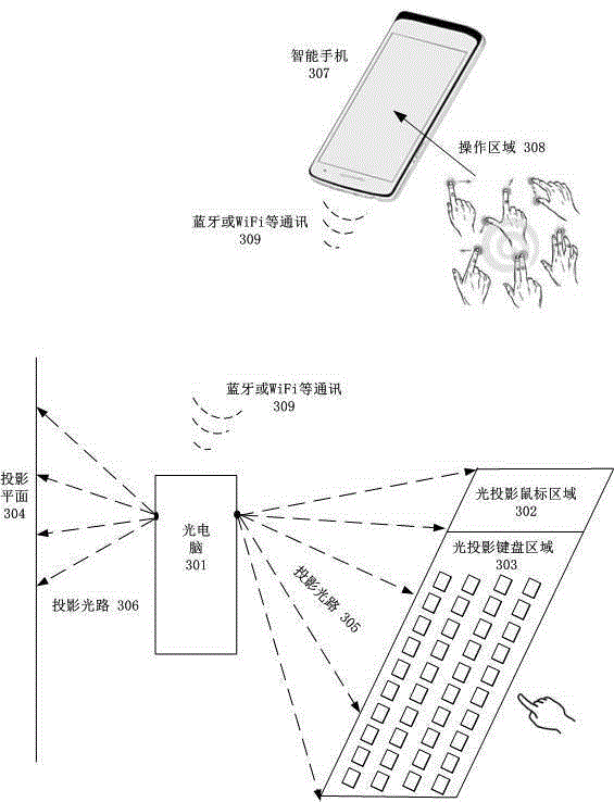
[0012] figure 1 The shown optical computer of the present invention based on smart phone control mainly includes two parts, namely optical computer 101 and smart phone 107 .

[0013] The optical computer 101 is the main machine, which is embedded with functions such as CPU, memory, hard disk, micro projection, optical projection keyboard module, WiFi, Bluetooth, USB, speaker, camera, and HDMI.

[0014] The miniature projection module in the optical computer 101 can project onto the projection plane through the projection optical path 106 to display the real content of the optical computer, thereby replacing the traditional computer monitor.

[0015] The optical projection keyboard module in the optical computer 101 can project the optical projection keyboard area 103 and the optical projection mouse area 102 through the projection o...


PUM


Abstract

The invention discloses a method for controlling an optical computer by applying a smart phone. The optical computer is a computer with a light projection screen, a light projection keyboard and a mouse area, wherein the light projection screen is used for displaying display content of the computer, and the light projection keyboard and the mouse area are used for realizing key position input operation and mouse control. The method for realizing control on key position input of the optical computer, mouse control and control on multi-fingered task by applying the smart phone can achieve the requirement that optical computer key position input and mouse control need to depend on a projection plane and widen the operation filed and the application scene of the optical computer.

Description

technical field [0001] The invention relates to a light projection computer controlled by a smart phone, in particular to the control and operation of the light projection computer using a smart phone based on wireless communication. Background technique [0002] The light projection computer includes three parts, namely the MiniPC (host) part, the miniature light projection part and the light projection keyboard and mouse area part. The MiniPC part is the entity of the optical computer, which is composed of CPU, memory, hard disk, WiFi, Bluetooth, speaker, camera and other computer links; the miniature optical projection is used to project the projection screen that the user can see, thus replacing the traditional display screen; The projected keyboard and mouse area is the projected part, and the user can perform keystroke input and mouse operations in the projected area. However, the light projection area needs to have a projection plane, such as a table, a coffee table,...

Claims


Application Information

Patent Timeline
Patent Type & Authority Applications(China)
IPC IPC(8): G06F1/16H04M1/725
Inventor 侯明鑫王俊博
Owner INTELLIGENCE YOCHU GUANGZHOU TECH CO LTD
Learn More