
Drag plate of knife grinder

A knife grinder and carriage technology, which is applied in the direction of grinding frame, grinding slide, grinding bed, etc., can solve the problems of poor lubrication effect, low feeding efficiency, complex structure, etc., and achieve high feeding efficiency , good lubricating performance and good wear resistance

Inactive Publication Date: 2016-02-10
陆如东
View PDF6 Cites 0 Cited by
  • Summary
  • Abstract
  • Description
  • Claims
  • Application Information

AI Technical Summary

Problems solved by technology

The traditional knife grinder carriage has complex structure, poor lubrication effect and low feed efficiency

Method used


Image

  • Drag plate of knife grinder
  • Drag plate of knife grinder
  • Drag plate of knife grinder

Examples


Embodiment Construction

[0015] The present invention will now be further described in conjunction with the accompanying drawings and preferred embodiments. These drawings are all simplified schematic diagrams, which only illustrate the basic structure of the present invention in a schematic manner, so they only show the configurations related to the present invention.

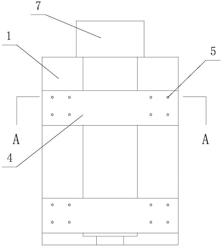
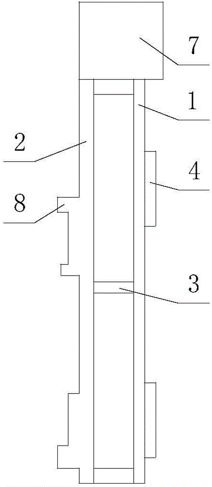
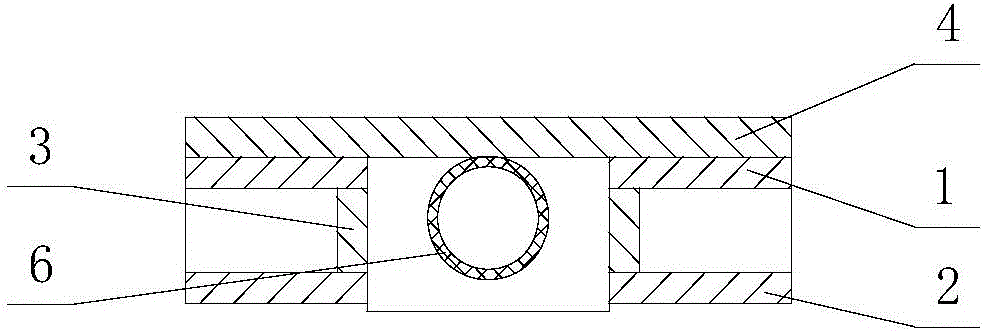
[0016] Such as figure 1 , figure 2 with image 3 A knife grinder carriage shown includes an upper plate 1 and a lower plate 2, a vertical plate 3 is connected between the upper plate 1 and the lower plate 2, and the upper plate 1 and the lower plate 2 are respectively arranged in parallel by two plates, In the cavity formed between the upper plate 1 and the vertical plate 3, there is a screw casing 6 which is sleeved on the screw and is slidably connected with the screw; The connected mounting plate 4 is provided with a motor box 7 at one end of the upper plate 1; the lower plate 2 is provided with a foot 8 connected with the work...


PUM


Abstract

The invention belongs to the technical field of knife grinder accessories and particularly relates to a drag plate of a knife grinder. The drag plate of the knife grinder comprises upper plate bodies and lower plate bodies. Vertical plates are connected between the upper plate bodies and the lower plate bodies. The two upper plate bodies and the two lower plate bodies are arranged in parallel. A lead screw sleeve arranged on a lead screw in a sleeving mode and connected with the lead screw in a sliding mode is arranged in a cavity formed between the upper plate bodies and the vertical plates. Two installing plates connected with other drag plates are fixed above the lead screw sleeve. A motor case is arranged at one ends of the upper plate bodies, and landing legs connected with a workbench are arranged on the lower plate bodies. The drag plate is reasonable in structure, the upper plate bodies, the lower plate bodies, the vertical plates, the installing plates and the lead screw sleeve are all made of stainless steel plates, abrasion resistance is good, the lead screw sleeve is arranged and matched with the lead screw, the lubricating performance is good, and feeding efficiency is high.

Description

technical field [0001] The invention relates to the technical field of knife sharpener accessories, in particular to a knife sharpener carriage. Background technique [0002] The carriage of the knife grinder is the most important feeding part of the knife sharpener. It is responsible for carrying the processing tool assembly and realizing the feeding of the workpiece. At present, the carriage of the knife sharpener is assembled by the main body of the carriage and the slider of the screw rod. The motor The rotating screw rod passes through the screw rod slider. When the motor drives the screw rod to rotate forward and reverse, the screw rod slider advances or retreats on the screw rod, so as to realize the forward and backward movement of the carriage body assembled with the screw rod slider. Give. The traditional knife grinder carriage has complex structure, poor lubrication effect and low feed efficiency. Contents of the invention [0003] The technical problem to be ...

Claims


Application Information

Patent Timeline
Patent Type & Authority Applications(China)
IPC IPC(8): B24B41/02
Inventor 陆如东
Owner 陆如东
Learn More