Automatic rail transport system of container wharf and operation method

A rail transportation and container technology, applied in the directions of transportation and packaging, conveyors, storage devices, etc., can solve the problems of increased cost, can only travel at both ends, and low horizontal transportation efficiency, and achieves improved work efficiency, high work efficiency, and practicality. wide range of effects

Active Publication Date: 2016-02-10
SHANGHAI HUAXING DIGITAL TECH
View PDF12 Cites 5 Cited by
  • Summary
  • Abstract
  • Description
  • Claims
  • Application Information

AI Technical Summary

Problems solved by technology

[0003] 1) The traffic of the group of automated means of transportation is complicated, and the efficiency of horizontal transportation is low;
[0004] 2) The gantry crane needs to run the hanging box for a long distance, which affects the loading and unloading efficiency of the yard;
[0005] 3) The storage yard layout needs to be perpendicular to the shore, and it is very difficult to transform the existing artificial wharf
[0007] The patent utilizes the shuttle car technology to realize the relay transportation of containers and automatic loading and unloading of containers. The use of rail trolleys instead of yard cranes for long-distance travel can increase the speed of container transportation at the terminal, but the traffic tracks are disconnected and can only be transported at both ends. To travel, it is necessary to use other equipment to transfer the container from one rail shuttle car to another rail shuttle car, and there must be a shuttle car on each track, which increases the cost

Method used


Image

  • Automatic rail transport system of container wharf and operation method
  • Automatic rail transport system of container wharf and operation method
  • Automatic rail transport system of container wharf and operation method

Examples


Embodiment 1

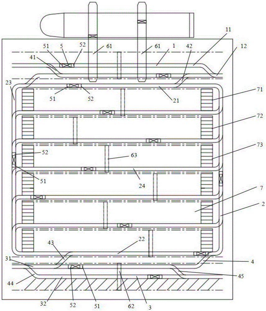
[0051] refer to figure 1, a structural schematic diagram of Embodiment 1 of the container terminal automated rail transportation system of the present invention. As shown in the figure, the transportation system includes at least one shore rail 1 parallel to the shore, at least one set of orbiting rails 2 arranged around the container yard, at least one dredging rail 3 behind the yard, at least A track shuttle car 5 and a plurality of transfer rails 4, and the shore rail and the surrounding rail 2 are connected through the transfer rail 4, and the surrounding rail 2 and the distribution rail 3 are connected through the transfer rail 4;

[0052] The rail shuttle car 5 has a container placement platform, which can run along the rails on the shore rail 1, the surrounding rail 2, the dredging rail 3, and the transfer rail 4, and the rail shuttle car 5 is provided with a control device (the Not shown), the control device accepts and transmits wireless command signals, controls the...

Embodiment 2

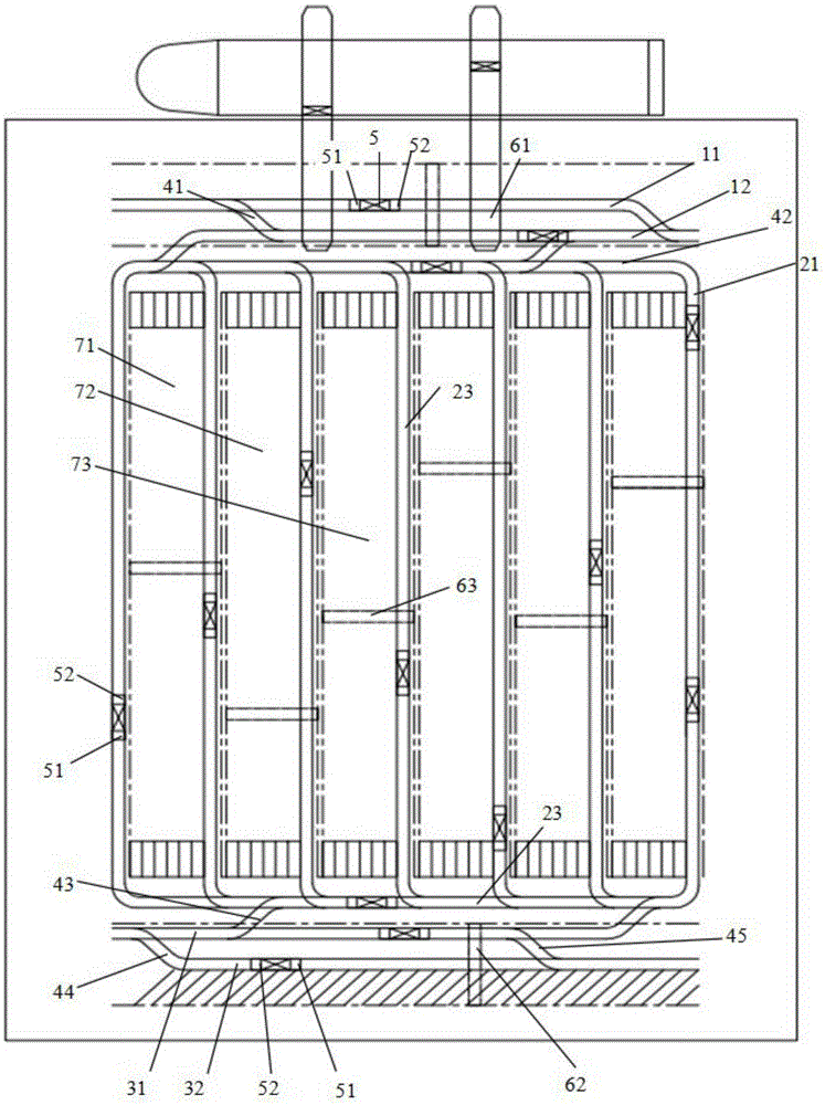
[0068] refer to figure 2 , a structural schematic diagram of Embodiment 2 of the container terminal automated rail transportation system of the present invention. As shown in the figure, the structure and content of the transportation system in this embodiment are basically the same as those in the first embodiment above, the only difference is that the storage yard is a vertical storage yard,

[0069] And there are a plurality of stack areas, each of which includes a plurality of stacking positions 7; the rail transportation system includes multiple sets of the surrounding tracks 2, and each set of the surrounding tracks 2 includes two vertical tracks and a plurality of Parallel tracks, and a stacking position 7 is arranged between every two parallel tracks, and each stack area is correspondingly provided with a set of surrounding tracks; the loading and unloading equipment 63 provided in the stockyard can travel to the parallel track. The rail shuttle car 5 on the track ca...

Embodiment 3

[0072] The present invention also proposes an operation method of the transportation system, comprising the following steps:

[0073] The process of transporting the container from the loading and unloading position on the shore to the unloading and unloading position behind the yard for unloading:

[0074] 1) The rail shuttle car 5 travels to the shore side loading and unloading position of the shore side track 1 to load and unload the container;

[0075] 2) The rail shuttle car 5 changes the track by exchanging the direction mode, and travels into the orbiting track 2 via the transfer track 4;

[0076] 3) The track shuttle car 5 travels unidirectionally along the orbital track 2 to a position where it connects with the transport track 3 through the transfer track 4;

[0077] 4) track shuttle car 5 is changed track by exchanging described direction mode, travels into dredging and transporting track 3 via transfer track 4;

[0078] 5) The track shuttle car 5 travels along th...


PUM


Abstract

The invention discloses an automatic rail transport system of a container wharf and an operation method. The automatic rail transport system comprises at least one onshore rail parallel to the shore side, at least one set of surrounding rails surrounding a container yard, at least one expedite transportation rail located behind the container yard, at least one rail shuttle vehicle and multiple adapting rails. The onshore rails and the surrounding rails are connected through the corresponding adapting rails, the surrounding rails and the expedite transportation rails are connected through the corresponding adapting rails, the surrounding rails are connected through the corresponding adapting rails, the adjacent onshore rails are connected through the corresponding adapting rails, and the adjacent expedite transportation rails are connected through the corresponding adapting rails. Each rail shuttle vehicle is provided with a container storing platform and can run along the rails, and each rail shuttle vehicle is further provided with a control device which receives and sends wireless command signals to control starting and stopping, speed modes and direction modes of the rail shuttle vehicle. The direction modes comprise the forwarding mode and the reversing mode. The running rails of the rail shuttle vehicles are changed by changing the direction modes. By means of the technical scheme, efficient and automatic rail transportation of containers can be achieved, transportation is simple, the application range is wide, and the work efficiency is high.

Description

technical field [0001] The invention relates to the technical field of container loading and unloading at a container terminal, in particular to an automatic rail transport system and an operation method for a container terminal. Background technique [0002] At present, the degree of automation of container terminals has been greatly improved, but there are still some deficiencies, mainly: [0003] 1) The traffic of the group of automated means of transportation is complicated, and the efficiency of horizontal transportation is low; [0004] 2) The gantry crane needs to run the hanging box for a long distance, which affects the loading and unloading efficiency of the yard; [0005] 3) The layout of the storage yard needs to be perpendicular to the shore, and it is very difficult to transform the existing artificial wharf. [0006] Refer to the Chinese patent "Shuttle carrier system for container terminal and method for transporting container thereof" whose patent number i...

Claims


Application Information

Patent Timeline
Patent Type & Authority Applications(China)
IPC IPC(8): B65G63/00B65G35/00
Inventor 袁爱进龙丽梁海玉
Owner SHANGHAI HUAXING DIGITAL TECH
Why Eureka
Try Eureka