Method for cutting of bonded substrate

A technology for bonding substrates and benchmarks. It is used in optics, glass manufacturing equipment, instruments, etc. It can solve problems such as poor substrates, movement, and incomplete separation of glass, and achieve the effect of improving separation.

Active Publication Date: 2016-02-10
MITSUBOSHI DIAMOND IND CO LTD
View PDF3 Cites 3 Cited by
  • Summary
  • Abstract
  • Description
  • Claims
  • Application Information

AI Technical Summary

Problems solved by technology

[0009] However, when using a scribing wheel to scribe the sealing layer of the liquid crystal substrate, due to the physical properties of the sealing layer, the scribing wheel loses its straightness while scribing and cannot move along the planned scribing line. Waiting and going in the other direction, making the substrate a poor issue
[0010] In addition, in the

Method used


Image

  • Method for cutting of bonded substrate
  • Method for cutting of bonded substrate
  • Method for cutting of bonded substrate

Examples


Embodiment Construction

[0035] In order to further explain the technical means and effects of the present invention to achieve the intended purpose of the invention, the specific implementation methods, methods, steps, Features and their functions are described in detail below.

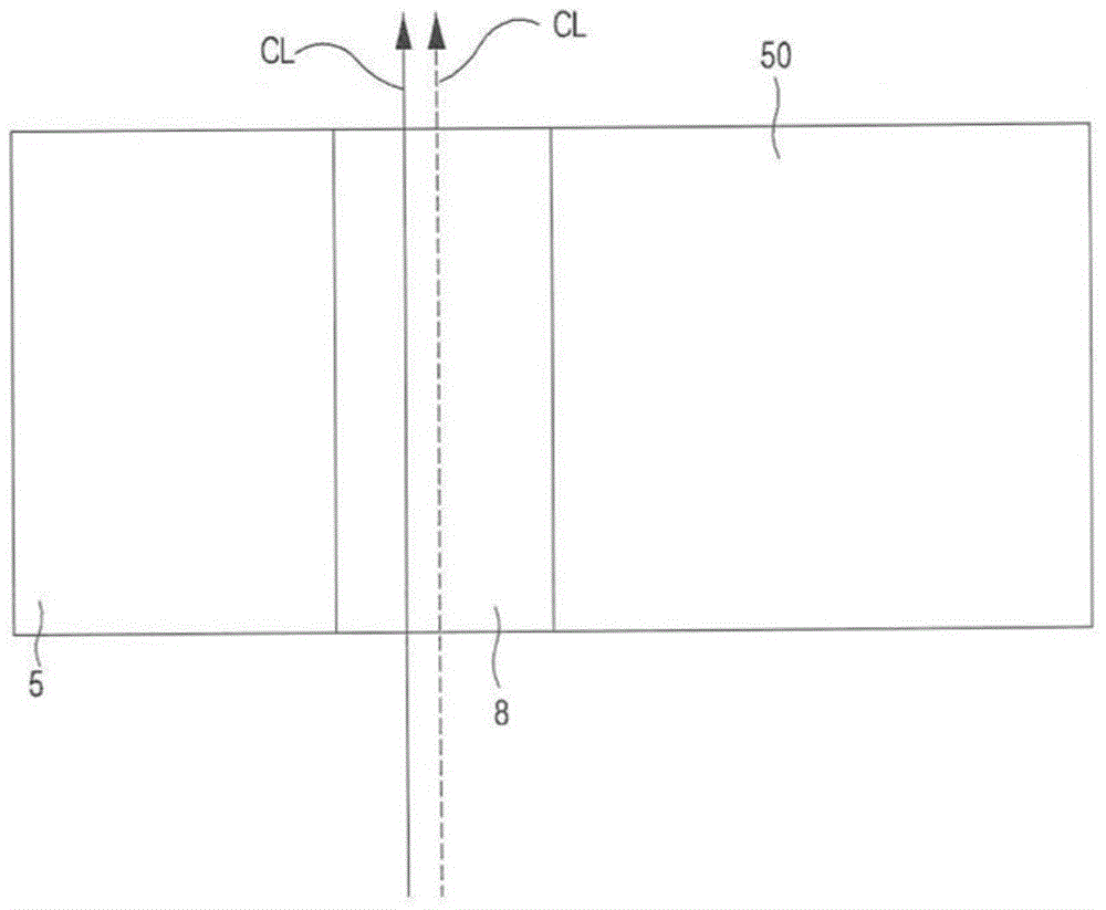
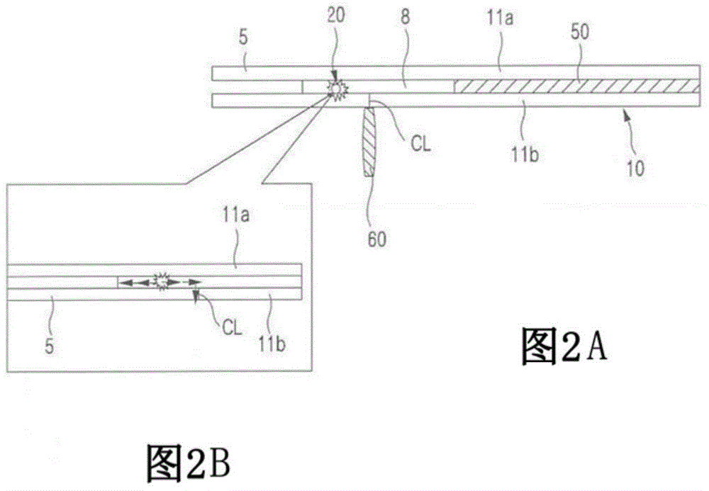
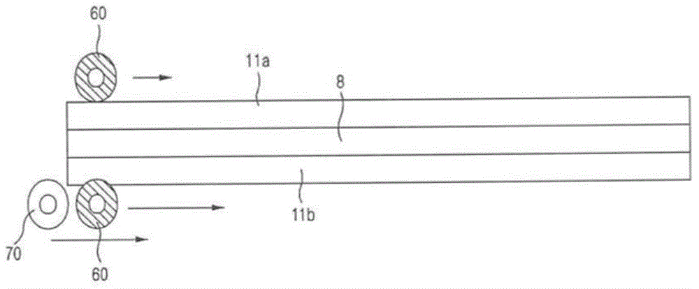
[0036] like figure 1 , Figure 2A and Figure 2B As shown, the bonded substrate 10 of this embodiment includes an upper glass portion 11a and a lower glass portion 11b, and a liquid crystal portion 50 is formed between the upper glass portion 11a and the lower glass portion 11b. Further, the outer periphery of the liquid crystal portion 50 is sealed with the sealing portion 8 so that the liquid crystal portion 50 does not leak liquid to the outside of the bonded substrate 10 .

[0037] In the frame portion of the bonded substrate 10 , there is an end material portion 5 which is an unnecessary portion. The sealing portion 8 is also included between the frame portions of the upper glass portion 11 a and the lower glass por...


PUM


Abstract

The present invention relates to a method for cutting of a bonded substrate, a useless material end part of the substrate can be furthest small when a liquid crystal substrate is cut, and a smooth cutting surface can be obtained. The method comprises the following steps of: scribing an upper glass part (11a) or a lower glass part (11b) on a sealing part (8) by using a scribe wheel (60) to form a scribe line (CL); irradiating laser to the sealing part (8) formed at the position isolated from the scribe line (CL) position with an interval to scribe; and scribing the residual glass parts without the scribe line (CL) by using the scribe wheel (60).

Description

technical field [0001] The present invention relates to a splitting method of a bonded substrate, in particular to a splitting method of a bonded substrate which can not only minimize unnecessary end material portions of the substrate but also obtain a smooth split section. Background technique [0002] In general, conventionally, only a scribing wheel is used when removing an unnecessary end material portion of a liquid crystal substrate. [0003] Specifically, in a general liquid crystal substrate, after the liquid crystal layer is filled between the upper glass portion and the lower glass portion, the frame portion of the liquid crystal layer is sealed with a sealing layer so that the liquid crystal layer does not leak to the outside. [0004] That is, a sealing layer is attached to the opposing surfaces of the upper glass portion and the lower glass portion, and the liquid crystal layer is sealed so that the liquid crystal layer does not flow out to the outside. [0005...

Claims


Application Information

Patent Timeline
IPC IPC(8): C03B33/02
CPCC03B33/023C03B33/03C03B33/037G02F1/1303Y02P40/57
Inventor 崔东光
Owner MITSUBOSHI DIAMOND IND CO LTD
Why Eureka
Try Eureka