
Vibration prevention footstand with alignment structure

A foot and base technology, applied in the field of anti-vibration feet with an alignment structure, can solve problems such as troublesome, easy to shift, unable to fix, skew, etc.

Inactive Publication Date: 2016-02-10
GAINIA SHANGHAI PATENT TECH LTD
View PDF11 Cites 54 Cited by
  • Summary
  • Abstract
  • Description
  • Claims
  • Application Information

AI Technical Summary

Problems solved by technology

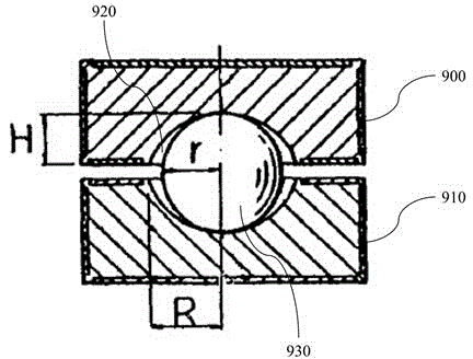
[0005] However, there are several deficiencies in the prior art. First: Since the upper seat 900 and the lower seat 910 are only connected by the point contact of the steel ball 930, when the anti-seismic feet are installed, the upper seat 900 and the lower seat 910 are easy to shift and cannot be fixed. , it is easy to cause skew during installation, and it is very troublesome to install the anti-seismic feet on the four corners of the equipment; second: when the installation is completed in the previous technology, it is difficult to judge and check whether the steel ball 930 is in the center position; third: The curvature of the groove 920 is only slightly larger than that of the steel ball 930. When a shock with a large amplitude like an earthquake occurs, it cannot effectively prevent the shock. Fourth: When the anti-seismic feet are installed on the four corners of the equipment, the height will often be caused by a slight error on the ground. Different, in the case of no height adjustment function, it will also cause uneven force on the anti-seismic feet and affect the shock-absorbing function

Method used


Image

  • Vibration prevention footstand with alignment structure
  • Vibration prevention footstand with alignment structure
  • Vibration prevention footstand with alignment structure

Examples


Embodiment Construction

[0040] In order to make the purpose, technical features and advantages of the present invention better understood by those skilled in the art and to implement the present invention, the technical features and implementation methods of the present invention are explained in the following description in conjunction with the accompanying drawings, and The preferred embodiments are listed for further description, but the following descriptions of the embodiments are not intended to limit the present invention, and the following diagrams are used to express the schematic representations related to the characteristics of the present invention.

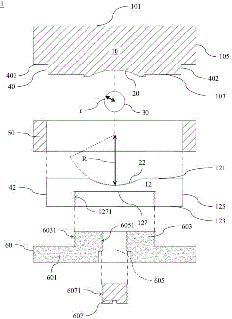
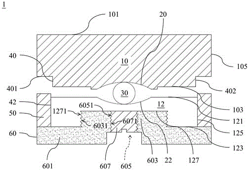
[0041] Please also see Figure 2A and Figure 2B , is an exploded view and an assembled schematic diagram of the first embodiment of the anti-vibration foot seat of the present invention. First, if Figure 2A As shown, the anti-shock base 1 of the first embodiment of the present invention includes: an upper base 10 with an upper surface 10...


PUM


Abstract

A vibration prevention footstand with an alignment structure comprises an upper base, a lower base, a sphere and a sliding sleeve. The sphere is arranged in an arc groove formed between the upper base and the lower base and makes point contact with the arc groove to achieve the vibration prevention effect. In addition, due to an inclined plane configured on the upper base and the sliding sleeve, the upper base and the lower base can be easily aligned and centered, and unnecessary correcting time waste is avoided.

Description

technical field [0001] The present invention relates to an anti-shock base, in particular to an anti-shock base with an alignment structure. Background technique [0002] In today's technologically advanced society, there are many sophisticated equipment, ranging from semiconductor manufacturing equipment to common household equipment. And because it is a sophisticated equipment, it needs to provide a certain degree of protection measures, so shock resistance has become one of the most important protection measures. [0003] There are many sources of equipment vibration, including: the vibration of the equipment itself during operation, the vibration caused by the environment, man-made vibration, natural vibration (earthquake), etc. The general shockproof is solved by the contact surface between the equipment and the ground. [0004] The previous technology of Taiwan's new specification 106223 "Anti-seismic feet for audio-visual equipment" discloses an anti-seismic foot su...

Claims


Application Information

Patent Timeline
IPC IPC(8): F16M7/00F16F15/02
Inventor 魏连峯黄建屏
Owner GAINIA SHANGHAI PATENT TECH LTD
Learn More