High-pressure liquid distributing system

A liquid separation and high pressure technology, applied in the field of high pressure liquid separation system of heat utilization equipment medium pipeline, can solve the problems of unsightly appearance, reduced equipment working efficiency, troublesome layout, etc., and achieves simple pipeline layout, small average variance and aesthetics. high effect

Inactive Publication Date: 2016-02-10
唐玉敏 +1
View PDF7 Cites 0 Cited by
  • Summary
  • Abstract
  • Description
  • Claims
  • Application Information

AI Technical Summary

Problems solved by technology

[0002] Existing high-power heat utilization equipment often has multiple heat dissipation pipes. In order to allow the medium pipeline to divide the flow in a balanced manner and improve the working efficiency of each heat dissipation pipe, most of the heat dissipation pipes are connected in parallel through the pipes, and each heat dissipation pipe is connected from the general inlet of the medium to the The pipes used for the main outlet are of the same length. This method will lead to the need to arrange more pipes for the heat pipes near the main inlet and outlet. Especially when multiple heat collecting plates are installed in a single row, the liquid separation method will It makes the project too bloated and unattractive, and at the same time causes the energy waste of the medium in the pipeline, the average variance of the heat dissipation of the radiator is not good, the overall working efficiency of the equipment is reduced, and the layout is troublesome; and the traditional liquid separation method requires heat accumulation The number of plates must be a power of 2 to be able to divide evenly, which greatly limits the applicable occasions and usage methods of heat collecting plates

Method used


Image

  • High-pressure liquid distributing system

Examples


Embodiment Construction

[0015] The present invention will be further described below with reference to the accompanying drawings.

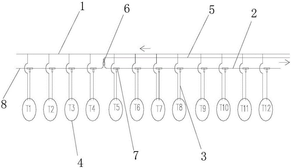
[0016] like figure 1 As shown, a high-pressure liquid distribution system provided in this embodiment includes an air inlet pipe 1 and a liquid outlet pipe 2. The air inlet pipe 1 communicates with twelve heat dissipation pipes 4 through equidistant pipes 3 and the connection port is located in the air inlet pipe 1. Arranged equidistantly above, the radiating pipes 4 are equidistantly connected to the liquid outlet pipes 2 through the equidistant pipes 3 respectively, and the connection ports are arranged equidistantly on the liquid outlet pipes 2, one-third of the liquid outlet pipes 2 and A total liquid outlet pipe 5 is communicated between the connecting pipes of the fourth and fifth radiating pipes which are communicated with the downstream section of the intake pipe.

[0017] The liquid outlet pipe 2 and the total liquid outlet pipe 5 are connected by a Y-shaped te...


PUM


Abstract

The invention discloses a high-pressure liquid distributing system and relates to the technical field of medium pipeline arrangement. By the adoption of the high-pressure liquid distributing system, the technical problems that according to existing heat utilization equipment, in order to make liquid be distributed uniformly through a high-pressure gas medium, the size of a pipeline is large, and the heat efficiency of the equipment is low are solved. The high-pressure liquid distributing system comprises a gas inlet pipe and a liquid outlet pipe. The high-pressure liquid distributing system is characterized in that the gas inlet pipe is communicated with a plurality of heat dissipation pipes through pipelines which are identical in length, and connecting ports are arranged in the gas inlet pipe at equal intervals; the heat dissipation pipes are communicated with the liquid outlet pipe through the pipelines which are identical in length, and connecting ports are arranged in the liquid outlet pipe at equal intervals; a main liquid outlet pipe is communicated to the position at one fifth or two fifths of the liquid outlet pipe and located between the two connecting pipelines of two heat dissipation pipes communicated with the downstream section of the gas inlet pipe. According to the high-pressure liquid distributing system, medium flow in the pipelines is distributed uniformly, all heat radiators can dissipate heat uniformly, the average variance of heat dissipation is small, the pipelines are arranged simply and reduced, the arrangement of the pipelines is high in attractiveness, and the number of heat collection plates can be adjusted flexibly.

Description

technical field [0001] The invention relates to the technical field of medium pipeline layout, in particular to a high-pressure liquid separation system suitable for medium pipelines of heat utilization equipment. Background technique [0002] Existing high-power heat utilization equipment often has multiple heat dissipation pipes. In order to allow the medium pipeline to divide the flow in a balanced manner and improve the working efficiency of each heat dissipation pipe, most of the heat dissipation pipes are connected in parallel through the pipes, and each heat dissipation pipe is connected from the general inlet of the medium to the The pipes used for the main outlet are of the same length. This method will lead to the need to arrange more pipes for the heat pipes near the main inlet and outlet. Especially when multiple heat collecting plates are installed in a single row, the liquid separation method will It makes the project too bloated and unattractive, and at the sa...

Claims


Application Information

Patent Timeline
Patent Type & Authority Applications(China)
IPC IPC(8): F28F9/22
Inventor 唐玉敏虞红伟
Owner 唐玉敏
Why Eureka
Try Eureka