Optical film and display device

An optical film, bottom surface technology, applied in optics, optical components, instruments, etc., can solve the problems of wear resistance and high optical gain of optical films

Active Publication Date: 2016-02-10
ZHANGJIAGANG KANGDE XIN OPTRONICS MATERIAL
View PDF9 Cites 2 Cited by
  • Summary
  • Abstract
  • Description
  • Claims
  • Application Information

AI Technical Summary

Problems solved by technology

[0006] The main purpose of the present invention is to provide an optical film and a display device to solve the problem that the optical film in the prior art cannot have high optical gain while having high wear resistance

Method used


Image

  • Optical film and display device
  • Optical film and display device
  • Optical film and display device

Examples


Embodiment 1

[0045] The optical film provided in this embodiment includes:

[0046] The lens layer has a bottom surface with a planar structure and is composed of a microlens array. The microlens array includes a plurality of lens structures arranged along the first direction. The lens structure is a plano-convex lens, the radius of curvature of the lens surface is r=15 μm, and the refractive index of the lens layer is n 1 =1.65, and the first direction is parallel to the bottom surface;

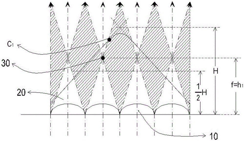
[0047] A prism layer, the prism layer is arranged on the lens layer away from the bottom surface, the prism layer is composed of a microprism array, the microprism array includes a plurality of prism structures arranged along the first direction, the refractive index of the prism layer is n 2 =1.35, the vertical distance H=28 μm between the intersection line of the extended surface of the side of the prism structure and the bottom surface, and the top angle of the prism structure is a rounded corner, and...

Embodiment 2

[0050] The optical film provided in this embodiment includes:

[0051] The lens layer has a bottom surface with a planar structure and is composed of a microlens array. The microlens array includes a plurality of lens structures arranged along the first direction. The lens structure is a plano-convex lens, the radius of curvature of the lens surface is r=9 μm, and the refractive index of the lens layer is n 1 =1.65, and the first direction is parallel to the bottom surface;

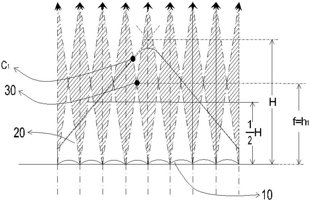
[0052] A prism layer, the prism layer is arranged on the lens layer away from the bottom surface, the prism layer is composed of a microprism array, the microprism array includes a plurality of prism structures arranged along the first direction, the refractive index of the prism layer is n 2 =1.35, the vertical distance H=28 μm between the intersection line of the extended surface of the side of the prism structure and the bottom surface, and the top angle of the prism structure is a rounded corner, and ...

Embodiment 3

[0055] The optical film provided in this embodiment includes:

[0056] The lens layer has a bottom surface with a planar structure and is composed of a microlens array. The microlens array includes a plurality of lens structures arranged along the first direction. The lens structure is a plano-convex lens, the radius of curvature of the lens surface is r=6 μm, and the refractive index of the lens layer is n 1 =1.65, and the first direction is parallel to the bottom surface;

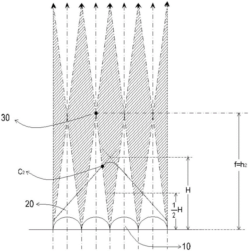
[0057] A prism layer, the prism layer is arranged on the lens layer away from the bottom surface, the prism layer is composed of a microprism array, the microprism array includes a plurality of prism structures arranged along the first direction, the refractive index of the prism layer is n 2 =1.35, the vertical distance H=28 μm between the intersection line of the extended surface of the side of the prism structure and the bottom surface, and the top angle of the prism structure is a rounded corner, and ...


PUM


Abstract

The invention provides an optical film and a display device. The optical film comprises a lens layer having a planar structure bottom, and composed of a microlens array, wherein the microlens array comprises a plurality of lens structures arranged in a first direction, and the first direction is parallel with the bottom; and a prism layer arranged on the lens layer distant from the bottom, and composed of a microprism array, wherein the microprism array comprises a plurality of prism structures arranged in the first direction, and the vertex angles of the prism structures are chamferings. The vertical distance between the focus point of a lens structure and the bottom is f; the vertical distance between the extension surface intersecting line of sides of a prism structure and the bottom is H, and f>1 / 2H. According to the invention, the top ends of the prism structures can drop in dark areas, forcing all rays of light to penetrate through the inclined surfaces of the prism structures, thereby avoiding beam angle convergence decrease of the optical film caused by curved top ends, and allowing the optical film to possess higher optical gains as well as greater wearability.

Description

technical field [0001] The invention relates to the technical field of thin films, in particular to an optical thin film and a display device. Background technique [0002] Optical films as brightness enhancement films disposed on flat panel displays are generally used to increase the light intensity in the front direction of the display. The main difficulty in using the above-mentioned optical films is that the surface microstructure is easily damaged by external force, thus causing flaws in the picture. In order to improve the image display effect of the optical film, it is generally necessary to improve the abrasion resistance and scratch resistance of the surface of the optical film. At present, the following treatment methods are usually used to achieve this: The first treatment method is to passivate the apex angle of the prism to reduce the damage of the microstructure. The possibility of damage can be improved to improve wear resistance. The second treatment method ...

Claims


Application Information

Patent Timeline
Patent Type & Authority Applications(China)
IPC IPC(8): G02B5/04
CPCG02B5/045
Inventor 丁清华
Owner ZHANGJIAGANG KANGDE XIN OPTRONICS MATERIAL
Why Eureka
Try Eureka