Power-on sequence control circuit, power-on sequence control method, control device and electronic terminal

A power-on sequence and control circuit technology, applied in program control, computer control, general control systems, etc., can solve problems such as high cost, unreliable power-on sequence control, etc., and achieve precise power-on delay control, accurate and safe The effect of electrical timing

Active Publication Date: 2016-02-10
恩平市赢力电子科技有限公司
View PDF6 Cites 12 Cited by
  • Summary
  • Abstract
  • Description
  • Claims
  • Application Information

AI Technical Summary

Problems solved by technology

[0007] In view of the above-mentioned shortcomings of the prior art, the object of the present invention is to provide a power-on sequence control circuit, a control method, a power supply device and an electronic terminal, which are used to solve the problem of unreliable or high-cost power-on sequence control in the prior art

Method used


Image

  • Power-on sequence control circuit, power-on sequence control method, control device and electronic terminal
  • Power-on sequence control circuit, power-on sequence control method, control device and electronic terminal
  • Power-on sequence control circuit, power-on sequence control method, control device and electronic terminal

Examples


Embodiment 1

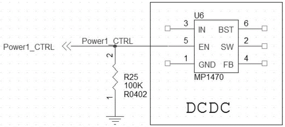
[0053] In one embodiment, as Figure 3a and 3b As shown, the power supply unit is a DC-DC power converter;

[0054] The power supply unit includes: a power supply chip (that is, U6 and U23 in the figure); the way that the first output terminal and the second output terminal are connected to the power supply chip includes: connecting to the enabling terminal (EN) of the power supply chip to control the power supply chip Output

[0055] Specifically, as shown in the figure, U6 and U23 are two-way DCDC (DC conversion power supply) respectively. The two-way power supply enable control output is determined by the time TA of Power1_CTRL and the time TB of Power2_CTRL respectively. Since there is a time difference between TA and TB, this time difference It is the timing of the output of the two power supplies.

[0056] In the figure, R25 and R242 are 100K weak pull-downs, which provide an initial state of no output for the enable pins of U6 and U23, so that U6 and U23 do not outpu...

Embodiment 2

[0058] In yet another embodiment, such as Figure 4a and Figure 4b As shown, the output terminal of the power supply unit (DC-DC) is led to the load terminal for connecting the load through the switching devices (Q5 and Q6). Determined by the time of Power2_CTRL, R241 and R243 are 100K weak pull-ups, which provide an initial state of cut-off for Q5 and Q6. When the MOS tube is cut off, the loads R240 and R245 are not powered on.

[0059] The timing control method of this embodiment is similar to that of Embodiment 1 above, but the control point is at the front end of the load (connected to Vout), that is, the DC-DC (direct current conversion power supply) is allowed to complete the no-load start first; the advantage of this control method is that it does not have Powering on the load can reduce the start-up inrush current and avoid damage to the load caused by the large inrush current, which is suitable for the sequence control requirements of the large load current.

[006...


PUM


Abstract

The invention provides a power-on sequence control circuit, a power-on sequence control method, a control device and an electronic terminal. The circuit comprises a trigger unit comprising a first trigger and a second trigger. Two input ends of each trigger are each connected with a time delay circuit, so that the time delay of an output power source control signal is the sum of the time delay of two input end signals. Power source drive signals are output through the output signals of the two triggers to drive power source units. The time delay differences between the power source drive signals form power-on sequences of the power source units, and accurate power-on time delay control and safe power-on sequences are realized.

Description

technical field [0001] The invention relates to the technical field of power supply control, in particular to a power-on sequence control circuit, a control method, a power supply device and an electronic terminal. Background technique [0002] In multi-power electronic systems, the integration level of IC chips increases, and the complexity and quantity also increase greatly. In order to ensure that the multi-power electronic system is powered on normally and can work normally, stably and reliably, it is necessary to control the power-on sequence of the power supply. At the same time, power sequence control is especially important to eliminate the latch-up effect of complex IC chips. Unreasonable power-on timing will affect the working life of IC chips and the working stability of multi-power electronic systems. [0003] In the prior art, there are mainly three schemes for controlling the power-on sequence of multiple power supplies: the first is to use the enable termina...

Claims


Application Information

Patent Timeline
Patent Type & Authority Applications(China)
IPC IPC(8): G05B19/042
CPCG05B19/042G05B19/0423G05B2219/25419
Inventor 裴志刚
Owner 恩平市赢力电子科技有限公司
Why Eureka
Try Eureka