
Control device for controlling the brakes of a towing vehicle/trailer combination

A technology of control device and parking brake, applied in the direction of brake transmission device, brake, automatic start device, etc., can solve problems such as danger

Active Publication Date: 2016-02-10
KNORR-BREMSE SYST FUER NUTZFAHRZEUGE GMBH
View PDF8 Cites 10 Cited by
  • Summary
  • Abstract
  • Description
  • Claims
  • Application Information

AI Technical Summary

Problems solved by technology

This can be dangerous especially on slopes

Method used


Image

  • Control device for controlling the brakes of a towing vehicle/trailer combination
  • Control device for controlling the brakes of a towing vehicle/trailer combination
  • Control device for controlling the brakes of a towing vehicle/trailer combination

Examples


Embodiment Construction

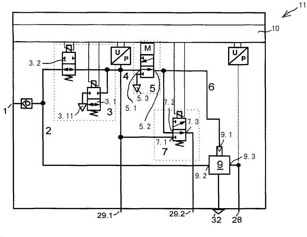
[0043] Control unit 11 of the pressure medium-actuated brake system of the tractor-trailer combination figure 1 The preferred embodiment shown in is arranged in a tractor vehicle, the pressure-medium-actuated brake system being, for example, a pneumatically-actuated brake system, and the control device is embodied here as a structural unit or module with its own housing. The braking device includes a parking brake device with a parking brake signal transmitter which can be adjusted manually, for example via an actuating lever (not shown here), the parking brake signal The transmitter controls the electronic control unit 10 of the control device 11 by means of electrical actuation signals via electrical signal lines. The electronic control unit 10 is preferably integrated into the control device 11 . Also integrated in the control device 11 is a valve unit controllable by the control unit 10 , which is supplied with compressed air from an air storage container (not shown here)...


PUM


Abstract

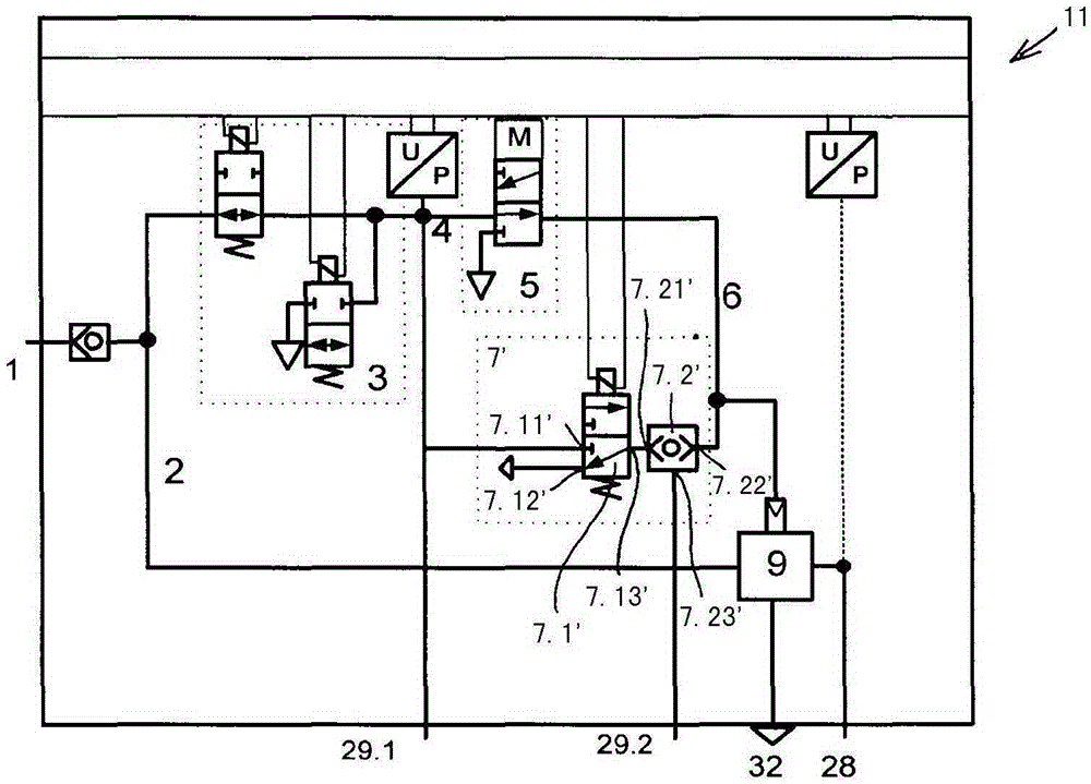
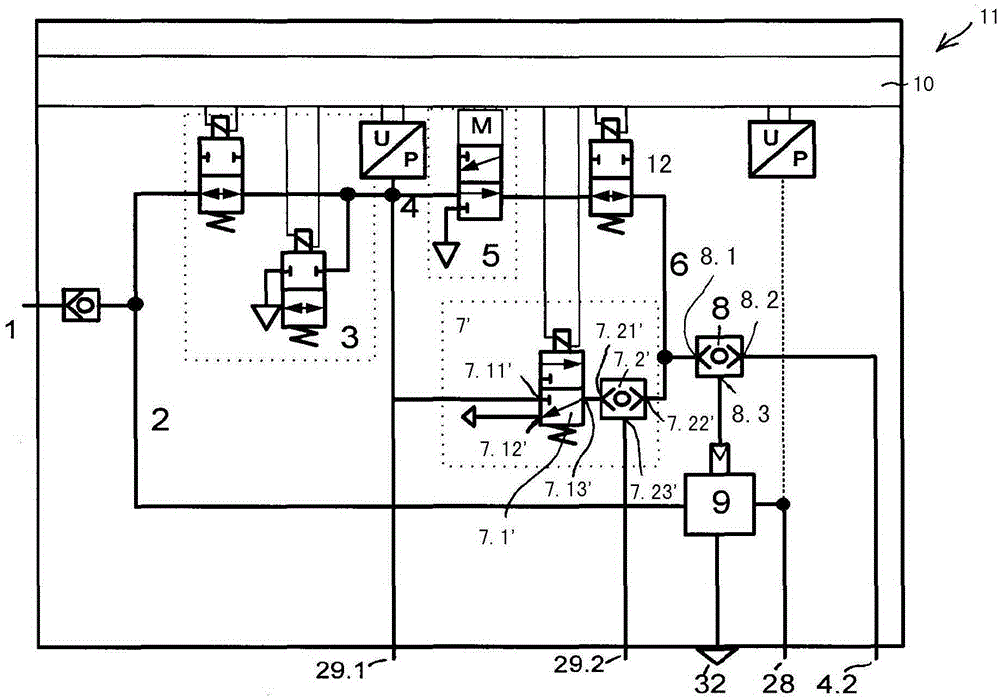
The invention relates to a control device for controlling at least the parking brake of a towing vehicle of a towing vehicle / trailer combination, said parking brake comprising at least one spring brake cylinder, and for controlling the service brake of a trailer of the towing vehicle / trailer combination, containing at least the following: a) a compressed air supply connection (1) which can be connected to a compressed air storage container, b) an air quantity boosting valve device (9), the inlet (9.2) of which can be connected to the compressed air supply connection (1), the outlet (9.3) of which can be connected to a working connection (28) with the at least one spring brake cylinder, and which has a pneumatic control inlet (9.1) for supplying a control pressure in order to control the pressure at the outlet (9.3) of the air quantity boosting valve device (9), c) an electrically actuatable bistable valve (5) with an inlet (5.1) which can be connected to the compressed air supply connection (1) and to an outlet (5.2) that can be connected to the control inlet (9.1) of the air quantity boosting valve device (9), the outlet (5.2) of the bistable valve being connectable either to the bistable valve inlet (5.1) or to a pressure sink (5.3), d) an electronic control unit (10) which is electrically connected to the bistable valve (5) and which controls the bistable valve (5), and e) at least two ventilatable or evacuatable connections (29.1, 29.2) for a trailer control valve device which controls the service brakes of the trailer, one connection (29.1) of the connections (29.1, 29.2) being ventilated and the other connection (29.2) of the connections (29.1, 29.2) being evacuated when the vehicle is parked and one connection (29.1) and the other connection (29.2) being ventilated when the vehicle is traveling, wherein f) the inlet (5.1) of the bistable valve (5) is connected to a connection (29.1). According to the invention, g) the outlet (5.2) of the bistable valve (5) is directly and constantly connected to the control inlet (9.1) of the air quantity boosting valve device (9), and h) a valve device (7; 7') is provided which can be at least partly electrically controlled by the control unit (10) and which is designed to connect the other connection (29.2) to the inlet (5.1) or to the outlet (5.2) of the bistable valve (5) or to a pressure sink (7.12').

Description

technical field [0001] The invention relates to a control device according to the preamble of claim 1 for controlling the parking brake of a tractor-trailer combination comprising at least one spring accumulator brake cylinder and for controlling the tractor-trailer combination Combined trailer service brakes. Background technique [0002] Commercial vehicles generally use so-called combination brake cylinders as brake actuators, in which combination brake cylinders in the form of active service brakes are coupled to service brake cylinders in the form of Spring accumulator brake cylinders for passive brakes. In the service brake cylinder, a service brake piston actuatable via a pressure medium is guided in a longitudinally displaceable manner, which delimits the service brake chamber and is connected to the service brake acting on the brake actuating element- Piston rod connection. In contrast, in the spring-accumulator brake cylinder, a spring-accumulator brake piston a...

Claims


Application Information

Patent Timeline
Patent Type & Authority Applications(China)
IPC IPC(8): B60T13/68B60T7/20B60T13/26B60T15/04
CPCB60T7/20B60T13/263B60T13/683B60T15/041
Inventor H·内梅特G·特赖基A·尤哈斯
Owner KNORR-BREMSE SYST FUER NUTZFAHRZEUGE GMBH
Learn More