Opening type interbody fusion cage

An intervertebral fusion device and fusion device technology, applied in the direction of spinal implants, etc., can solve problems such as difficult removal, difficult implantation, patient trauma, etc., and achieve the effect of simple operation and large contact area

Active Publication Date: 2016-02-17
BEIJING FULE SCI & TECH DEV +1
View PDF6 Cites 9 Cited by
  • Summary
  • Abstract
  • Description
  • Claims
  • Application Information

AI Technical Summary

Problems solved by technology

Intervertebral fusion includes autologous bone graft fusion and allograft bone graft fusion. Due to the limited source of autologous bone, increased donor site trauma, and inability to provide timely mechanical stability, the clinical application of intervertebral fusion is limited, while allograft bone graft not only High cost, limited quantity, virus transmission and immune rejection caused by allogeneic bone are also the main reasons for its widespread clinical application
In recent years, in order to increase the fusion rate of bone grafts, reduce the dependence on external fixation, and improve and maintain the curvature of the spine, distraction-type intervertebral fusion devices have emerged as the times require, but the existing distraction-type intervertebral fusion Most of them need to implant two fusion devices at the same time, so it is necessary to resect the bilateral facet joints, which seriously damages the posterior structure of the lumbar spine and affects the postoperative stability of the lumbar spine. The contact area is small, and it is easy to loose and unstable between the spine after implantation, which affects the implantation effect, and it is also difficult to remove, which is easy to cause trauma to the patient

Method used


Image

  • Opening type interbody fusion cage
  • Opening type interbody fusion cage
  • Opening type interbody fusion cage

Examples


Embodiment Construction

[0035] In order to further illustrate the present invention, the distraction-type intervertebral fusion device provided by the present invention will be described in detail below with reference to the accompanying drawings and embodiments, but they should not be understood as limiting the protection scope of the present invention.

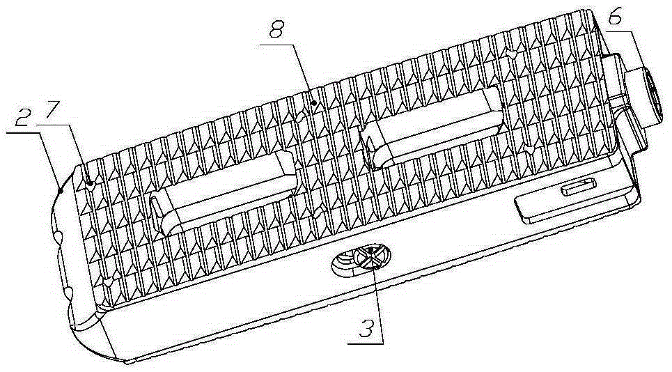
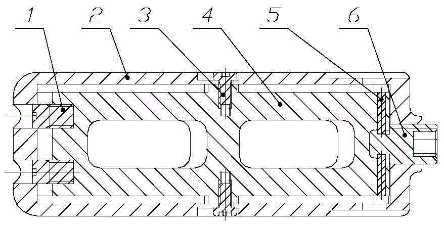
[0036] The invention provides a distraction type intervertebral fusion device, such as figure 1 , 2 , 3, 5, 6, 8, 10, and 11, including fusion device body 2, push block 4, top wire 6 and end cap 8; fusion device body 2 is a rectangular frame shape, and push block 4 is installed on the fusion device body 2. Inside, there are two end caps 8, which are respectively arranged at the top and bottom positions of the fusion device body 2. One end surface of the fusion device body 2 is provided with a rectangular boss 16, and the other end transitions into a pointed shape. The rectangular boss 16 There is a first threaded hole 17 in the middle, and one end...


PUM


Abstract

The invention provides an opening type interbody fusion cage. The opening type interbody fusion cage comprises a fusion cage body, a push block, a jackscrew and two end covers. The fusion cage body is in a rectangular frame shape, the push block is installed in the fusion cage body, the two end covers are arranged at the top and the bottom of the fusion cage body respectively, a rectangular boss is arranged on one end face of the fusion cage body, the other end of the fusion cage body is in a transitional sharp corner shape, the jackscrew is arranged in the middle of the rectangular boss and connected with the rectangular boss through threads, and wedge-shaped protrusions are arranged at the two ends and the middle poison of the push block respectively. In a working state, the ends, close to the jackscrew, of the wedge-shaped protrusions are platforms, and a first round hole matched with the jackscrew in installation is formed in the platform of the wedge-shaped protrusion, close to the jackscrew, of the push block. Tooth-shaped protrusions are evenly distributed on the upper surfaces of the end covers, and wedge-shaped grooves matched with the wedge-shaped protrusions are formed in the two ends and the middle of the bottoms of the end covers. The jackscrew is rotated to drive the push block to move to one end, and the wedge-shaped protrusions are made to slide along the slopes of the wedge-shaped grooves to open the end covers in parallel. A lateral approach implantation method can be adopted, surgery is simple, damage to the spine is very small, and higher stability is achieved.

Description

technical field [0001] The invention relates to a distraction type intervertebral fusion device, which belongs to the field of medical equipment and is suitable for lateral lumbar intervertebral fusion surgery. Background technique [0002] Lumbar intervertebral fusion is one of the methods to treat spinal diseases, and more and more people receive intervertebral fusion every year. Intervertebral fusion includes autologous bone graft fusion and allograft bone graft fusion. Due to the limited source of autologous bone, increased donor site trauma, and inability to provide timely mechanical stability, the clinical application of intervertebral fusion is limited, while allograft bone graft not only High cost, limited quantity, virus transmission and immune rejection caused by allograft bone are also the main reasons for its wide application in clinic. In recent years, in order to increase the fusion rate of bone grafts, reduce the dependence on external fixation, and improve a...

Claims


Application Information

Patent Timeline
Patent Type & Authority Applications(China)
IPC IPC(8): A61F2/44
Inventor 王雅玲黄锡艺鲁文胜仇万裕张磊
Owner BEIJING FULE SCI & TECH DEV
Why Eureka
Try Eureka