Dynamic-pressurizing-locked bone screw and use method thereof

A bone screw, dynamic technology, applied in the field of dynamic compression locking bone screw, can solve the problems of internal fixation fatigue fixation, internal fixation failure, failure, etc., to avoid bone nonunion, fast postoperative recovery, and promote callus the formation of the effect

Inactive Publication Date: 2015-12-30
山东康盛医疗器械股份有限公司
View PDF8 Cites 5 Cited by
  • Summary
  • Abstract
  • Description
  • Claims
  • Application Information

AI Technical Summary

Problems solved by technology

Similarly, failure of the internal fixation may also occur if the fracture is incompletely united. This is due to the fact that the internal fixation needs to continue to bear the load in the absence of bony union, which may eventually lead to internal fixation fatigue or failure of the fixation.

Method used


Image

  • Dynamic-pressurizing-locked bone screw and use method thereof
  • Dynamic-pressurizing-locked bone screw and use method thereof

Examples


Embodiment 1

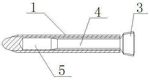
[0019] Embodiment 1: A dynamic compression locking bone screw as shown in the accompanying drawings, which includes a screw sleeve 1 and a screw core, the screw core includes a top cap 3, a polished rod 4, and a nail head 5, and the screw sleeve 1 is sleeved on the polished rod 4 , the periphery of the nail head 5, a gap is arranged between the screw sleeve 1 and the polished rod 4, and the screw sleeve 1 is connected with the nail head 5.

[0020] The screw core and the screw sleeve 1 are fixed together by interference fit to form a dynamic elastic fretting structure in which the screw sleeve can move radially along the screw core.

[0021] Further, the screw mandrel end is provided with a polished rod 4, the nail head 5 is an interference assembly structure, the screw sleeve 1 is a closed inner hollow structure with a light hole inside the closed end, and the screw core and the screw sleeve 1 pass through the The form of positive fit is fixed together.

[0022] The end of t...

Embodiment 2

[0028] Embodiment 2: A dynamic compression locking bone screw, which includes a screw sleeve 1 and a screw core, the screw core includes a top cap 3, a polished rod 4, and a nail head 5, and the screw sleeve 1 is set on the periphery of the polished rod 4 and the nail head 5, There is a gap between the screw sleeve 1 and the polished rod 4 , and the screw sleeve 1 is connected with the nail head 5 .

[0029] The screw core and screw 1 set are fixed together through internal and external thread connections, forming a dynamic elastic micro-movement structure in which the screw set 1 can move radially along the screw core.

[0030] Further, the screw mandrel end is provided with a polished rod 4, the nail head 5 is an external thread structure, the screw sleeve 1 is a closed inner hollow structure at one end, and the closed end is internally threaded, and the screw core and the screw sleeve 1 are fixed in the form of an internal and external thread connection together. The metho...


PUM


Abstract

The invention provides a dynamic-pressurizing-locked bone screw and a use method thereof. The dynamic-pressurizing-locked bone screw comprises a screw sleeve and a screw core, wherein the screw core comprises a top cap, an unthreaded rod and a screw head, the screw sleeve sleeves the periphery of the unthreaded rod and the periphery of the screw head, a gap exists between the screw sleeve and the unthreaded rod, and the screw sleeve is connected with the screw head. Through the dynamic-pressurizing-locked bone screw, which achieves that a fracture site moves almost parallel to the fracture site through fixing lateral cortices, the stress concentration of the root of the screw can be avoided, the screw can be prevented from rupture, and meanwhile, micro friction is provided for the broken ends of a fractured bone so as to faster promote the formation of calluses, and thus, a faster and stable healing process is provided.

Description

technical field [0001] The invention relates to the field of medical equipment, in particular to a dynamic pressure-locking bone screw for internal fixation of human fractures and a method of use thereof. Background technique [0002] At present, the fracture fixation used clinically has generally changed from the original ordinary ball-head screw to thread-head locking screw. Locking screw is generally recognized clinically for its good supporting performance and bridging performance. The increased strength of bone fixation, and its ability to provide a more biomechanically friendly fixation device, has contributed to the rapid clinical acceptance of this technique. The biological fixation of comminuted fractures by locking and fixation relies on the secondary fracture healing mode of callus formation, which is generated by micromotion stimulation between the fracture fragments. Secondary fracture healing can be promoted by active or passive dynamization. Conversely, if t...

Claims


Application Information

Patent Timeline
Patent Type & Authority Applications(China)
IPC IPC(8): A61B17/86
CPCA61B17/8685A61B17/861A61B17/8625
Inventor 黄河清
Owner 山东康盛医疗器械股份有限公司
Why Eureka
Try Eureka