Supercharge Your Innovation With Domain-Expert AI Agents!

Injection mould and degating method thereof

A technology for injection molds and nozzles, applied in the field of injection molds, can solve problems such as high production costs, a large amount of labor and trimming time, and low production efficiency, and achieve the effects of long service life, saving production time, and reducing labor costs

Active Publication Date: 2016-02-17
RIFENG ENTERPRISE FOSHAN CO LTD +2
View PDF8 Cites 0 Cited by
  • Summary
  • Abstract
  • Description
  • Claims
  • Application Information

AI Technical Summary

Problems solved by technology

This type of mold is equipped with a large nozzle. After the products injected by this type of mold are ejected, the nozzle handle needs to be manually trimmed to separate the product from the nozzle handle. This requires a lot of labor and trimming time, and the production efficiency is low. and higher production costs

Method used


Image

  • Injection mould and degating method thereof
  • Injection mould and degating method thereof
  • Injection mould and degating method thereof

Examples


Embodiment Construction

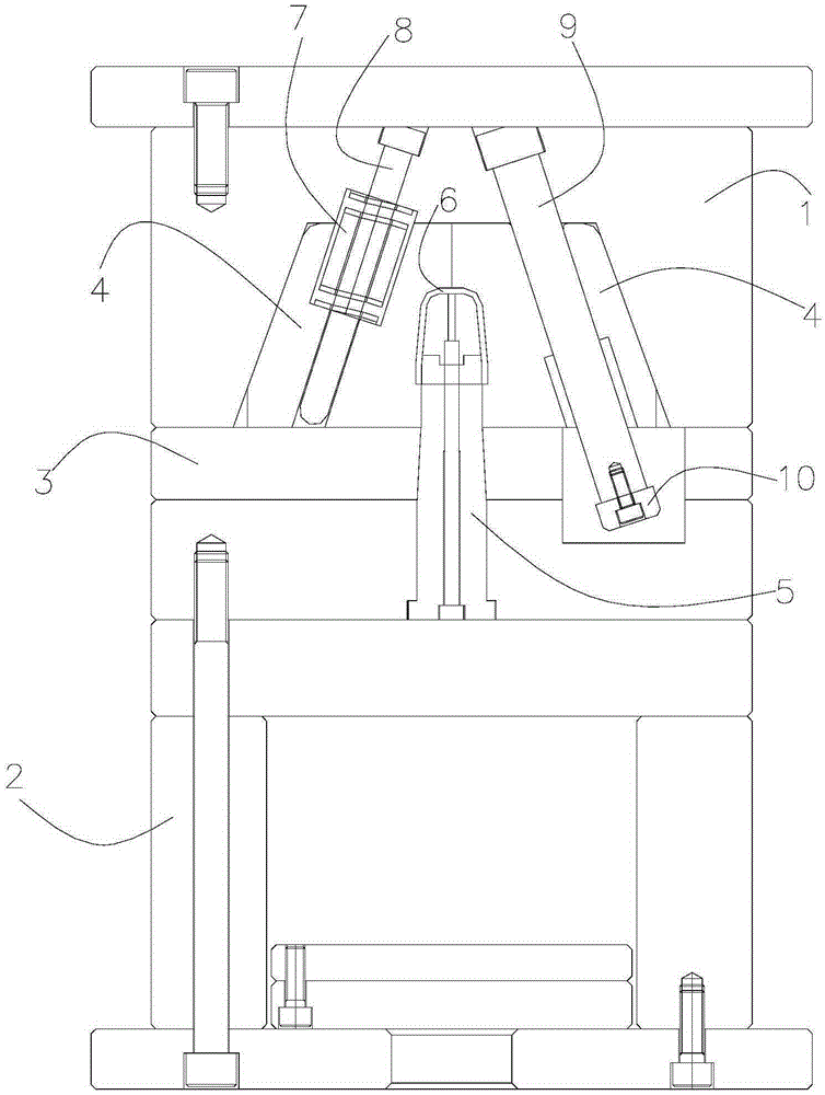
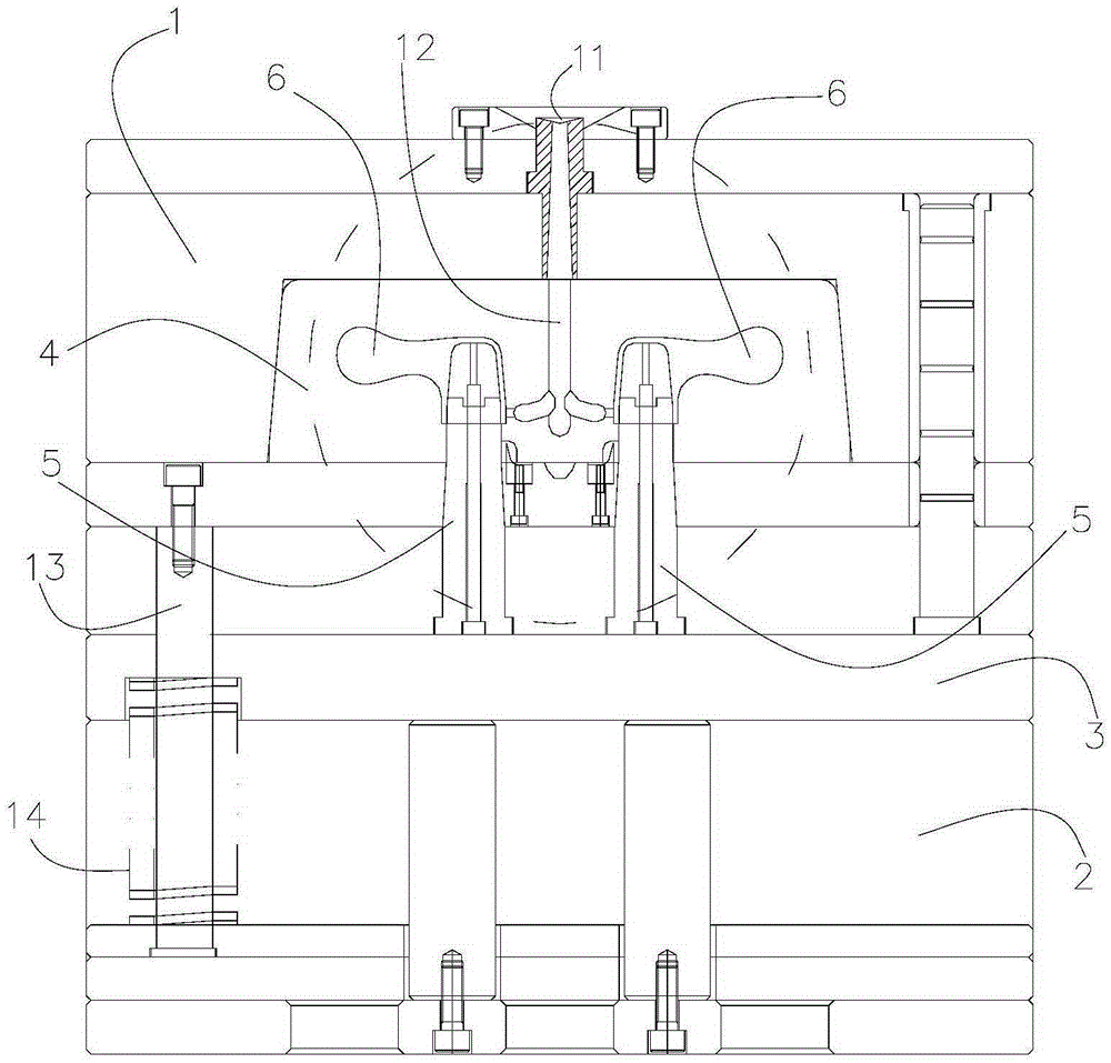
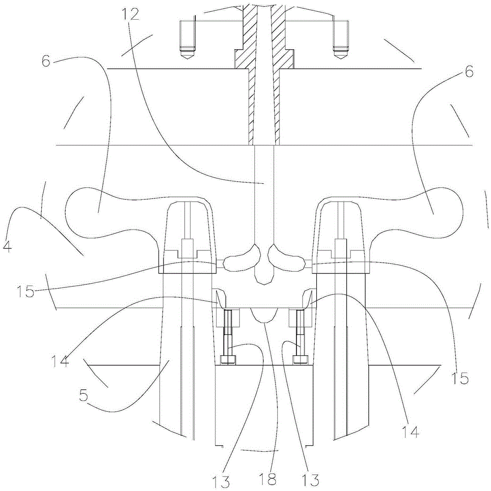
[0029] Such as Figure 1-6 As shown, an injection mold includes a front mold 1, a rear mold 2, a push plate 3 located between the front mold 1 and the rear mold 2, and two pieces are embedded on the side of the front mold 1 facing the push plate 3. Slider 4, along the direction of the front and rear die 2, the slide block 4 is slidably connected with the front die 1 through an elastic device, and the rear die 2 is provided with a rear mold core 5 that passes through the push plate 3 and protrudes from the front die 1, and the front and rear dies 2. When the mold is closed, the elastic device is in a compressed state, and a mold cavity 6 is formed between the two slide blocks 4 and the rear mold core 5, and a nozzle 11 is opened on the outer surface of the front mold 1. There is a flow channel 12 connecting the nozzle 11 and the mold cavity 6, the flow channel 12 is provided with a flow channel opening 15 leading to the mold cavity 6, and a nozzle cutter is provided on the push...


PUM


Abstract

The invention discloses an injection mould and a degating method thereof. The injection mould comprises a front mould body, a rear mould body and a push board arranged between the front mould body and the rear mould body, wherein two sliding blocks are embedded into the side, facing the push board, of the front mould body; the sliding blocks are in sliding connection with the front mould body through elastic devices in the direction of the front mould body and the rear mould body; a rear mould core penetrating through the push board and protruding towards the front mould body is arranged on the rear mould body; when the front mould body and the rear mould body are combined, the elastic devices are in a compressed state; a mould cavity is formed among the two sliding blocks and the rear mould core; a sprue is formed in the outer surface of the front mould body; a runner communicating the sprue with the mould cavity is arranged inside the front mould body and provided with a runner opening leading to the mould cavity; a water gap cutter is arranged on the push board and corresponds to the runner opening. Separation of a product and a water gap material handle is achieved after the product obtained after injection molding comes out of the mould, manual shearing of a water gap material after mould stripping is not needed, the production time of the product is shortened, the production efficiency is improved, and the labor cost is reduced.

Description

technical field [0001] The invention mainly relates to the technical field of injection molds, in particular to an injection mold and a method for cutting nozzles thereof. Background technique [0002] At present, the injection mold adopts a two-slider package cavity structure (or Huff mold), and the glue feeding method is mostly a large nozzle from the side of the cavity. The advantages are: fast injection molding, low pressure, and strong pressure holding capacity. And the pressure loss is small, suitable for plastics with poor fluidity. This type of mold is equipped with a large nozzle. After the products injected by this type of mold are ejected, the nozzle handle needs to be manually trimmed to separate the product from the nozzle handle. This requires a lot of labor and trimming time, and the production efficiency is low. And the production cost is higher. Contents of the invention [0003] The invention provides an injection mould. After the product is molded by t...

Claims


Application Information

Patent Timeline
IPC IPC(8): B29C45/38
CPCB29C45/38
Inventor 赵欣李代叙欧伟基曹勇
Owner RIFENG ENTERPRISE FOSHAN CO LTD
Features
  • R&D
  • Intellectual Property
  • Life Sciences
  • Materials
  • Tech Scout
  • Unparalleled Data Quality
  • Higher Quality Content
  • 60% Fewer Hallucinations
Learn More