Scroll compressor

A scroll compressor and moving scroll technology, applied in the field of compressors, can solve problems such as loose sealing

Active Publication Date: 2016-02-17
ZHUHAI GREE REFRIGERATION TECH CENT OF ENERGY SAVING & ENVIRONMENTAL PROTECTION
View PDF7 Cites 7 Cited by
  • Summary
  • Abstract
  • Description
  • Claims
  • Application Information

AI Technical Summary

Problems solved by technology

[0004] The present invention aims to provide a scroll compressor to solve the problem of poor sealing of scroll compressors in the prior art under low pressure ratio working conditions

Method used


Image

  • Scroll compressor
  • Scroll compressor
  • Scroll compressor

Examples


Embodiment Construction

[0023] Hereinafter, the present invention will be described in detail with reference to the accompanying drawings and in conjunction with embodiments. It should be noted that the embodiments in the present application and the features of the embodiments may be combined with each other in the case of no conflict.

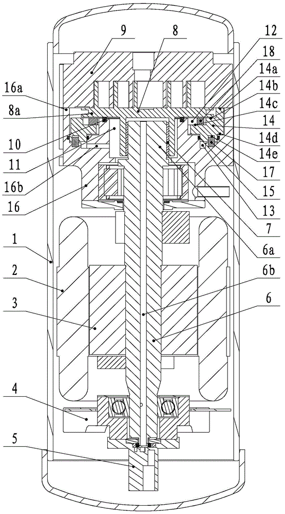
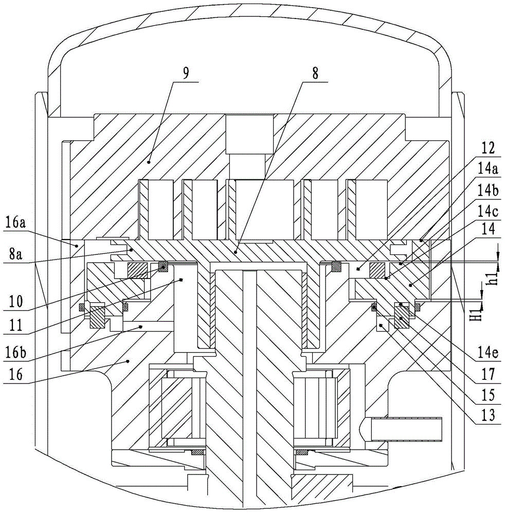
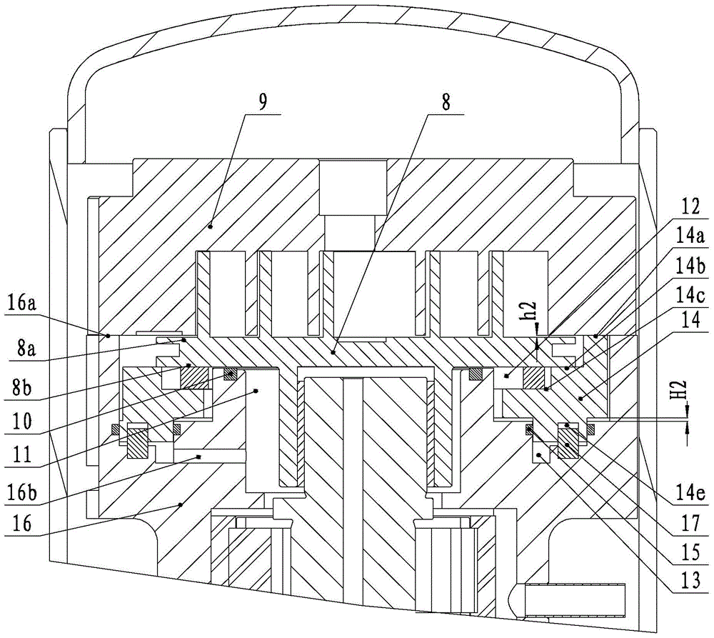
[0024] like Figures 1 to 5 As shown, according to the embodiment of the present invention, the scroll compressor includes an upper bracket 16 , a fixed scroll 9 , an orbiting scroll 8 and a flexible thrust member 14 .

[0025] The upper bracket 16 includes an outer ring platform 16a and an inner ring platform 16c, and a receiving groove is formed between the outer ring platform 16a and the inner ring platform 16c. to accommodate the flexible thrust member 14 . The fixed scroll 9 is fixedly arranged on the outer ring base 16a, and is in sealing contact with the upper end surface of the outer ring base 16a.

[0026] The movable scroll 8 is arranged between the uppe...


PUM


Abstract

The invention provides a scroll compressor. The scroll compressor comprises an upper support, a static scroll plate, a movable scroll plate and a flexible thrusting piece. The upper support comprises an outer ring table, an inner ring table and a containing groove. The static scroll plate is arranged on the outer ring table. The movable scroll plate is arranged between the upper support and the static scroll plate and provided with an end plate. A first sealing piece is arranged between the end plate and the inner ring table. The space between the back face of the movable scroll plate and the upper support is divided into a first back pressure cavity and a second back pressure cavity through the first sealing piece. The pressure of the first back pressure cavity is higher than that of the second back pressure cavity. The flexible thrusting piece is movably arranged in the containing groove in the axial direction and is provided with limiting portions and thrusting portions. The upper end faces of the limiting portions are matched with the static scroll plate. The upper end faces of the thrusting portions are lower than the upper end faces of the limiting portions. Second sealing pieces are arranged between the flexible thrusting piece and the containing groove. A third back pressure cavity is formed between the flexible thrusting piece and the containing groove through the second sealing pieces. The third back pressure cavity is communicated with the first back pressure cavity through a communication hole. The airtightness of the scroll compressor can be improved through the scroll compressor.

Description

technical field [0001] The present invention relates to the field of compressors, in particular to a scroll compressor. Background technique [0002] In a scroll compressor with a high-pressure cavity structure, in order to ensure the tightness of the compression cavity, a discharge pressure or intermediate pressure (ie back pressure) higher than the suction pressure is usually introduced on the back of the movable scroll, so that the movable scroll The rotating disk and the stationary scroll are tightly fitted together. However, when the compressor operates at a higher pressure ratio, if the contact force between the movable scroll and the fixed scroll is too large, the scrolls will easily engage, which will increase wear and reduce reliability. For this reason, the back pressure should not be too large in the design. However, when the compressor operates in the low pressure ratio condition, the back pressure will not be able to compress the movable scroll, the movable sc...

Claims


Application Information

Patent Timeline
Patent Type & Authority Applications(China)
IPC IPC(8): F04C18/02F04C27/00
Inventor 刘双来康小丽李冬元陈肖汕刘韵律刚马英超
Owner ZHUHAI GREE REFRIGERATION TECH CENT OF ENERGY SAVING & ENVIRONMENTAL PROTECTION
Why Eureka
Try Eureka