Speed change mechanism of automatic two-gear transmission

A technology of automatic transmission and speed change mechanism, which is applied in the direction of mechanical equipment, transmission, belt/chain/gear, etc., can solve the problems of low efficiency, high cost, and low transmission efficiency of the drive motor, and avoid excessive discharge current, The effect of low production cost and high transfer efficiency

Inactive Publication Date: 2016-02-17
HUNAN UNIV
View PDF5 Cites 7 Cited by
  • Summary
  • Abstract
  • Description
  • Claims
  • Application Information

AI Technical Summary

Problems solved by technology

The selection of the speed ratio of the single speed ratio reduction device is a trade-off between the above two working conditions. Although the drive motor itself has a certain speed regulation function, it is difficult to make the vehicle meet the performance requirements of low-speed climbing and high-speed driving at the same time.
In addition, when a vehicle equipped with a reduction gear with a single speed ratio is started or working at the highest speed, the drive motor is in a low-efficiency range, which has an adverse effect on the cruising range and life of the battery.
[0004] The existing AMT gearbox needs to cut off the power through the clutch when shifting gears, and the synchronizer is driven by the shift motor, which is difficult to control; the existing planetary gear AT gearbox uses a wet clutch to shift gears, which needs to be matched with a complex hydraulic system , the transmission efficiency is low, and the cost is high; the existing dual-clutch gearbox uses a wet clutch or a dry clutch to shift gears, and the control system is complex and costly

Method used


Image

  • Speed change mechanism of automatic two-gear transmission
  • Speed change mechanism of automatic two-gear transmission
  • Speed change mechanism of automatic two-gear transmission

Examples


Embodiment Construction

[0029] The technical solutions of the present invention will be clearly and completely described below in conjunction with the accompanying drawings. Apparently, the described embodiments are some of the embodiments of the present invention, but not all of them. Based on the embodiments of the present invention, all other embodiments obtained by persons of ordinary skill in the art without making creative efforts belong to the protection scope of the present invention.

[0030] In the description of the present invention, it should be noted that the terms "center", "upper", "lower", "left", "right", "vertical", "horizontal", "inner", "outer" etc. The indicated orientation or positional relationship is based on the orientation or positional relationship shown in the drawings, and is only for the convenience of describing the present invention and simplifying the description, rather than indicating or implying that the referred device or element must have a specific orientation, ...


PUM


Abstract

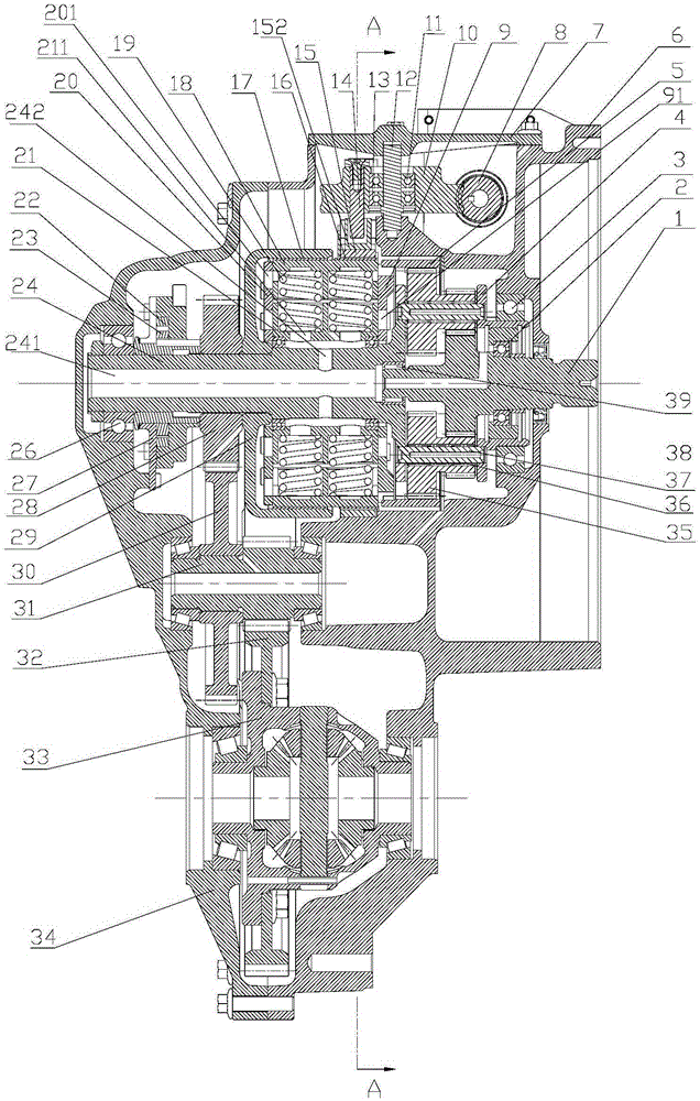
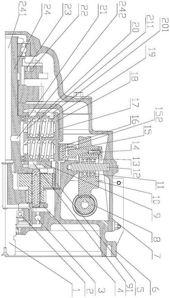
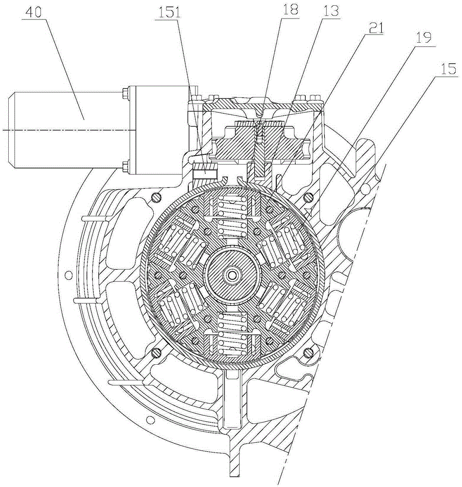
The invention provides a speed change mechanism of an automatic two-gear transmission. The speed change mechanism comprises a shell, a planetary gear system, a brake hub, a brake shoe assembly, a brake belt, a turbo-worm mechanism, a gear-shifting motor and a differential mechanism. The planetary gear system comprises a sun wheel, a compound planetary gear, an inner gear ring and a planetary carrier shaft. The sun wheel serves as the power input end. The sun wheel is connected with the planetary carrier shaft through the compound planetary gear, and meanwhile the sun wheel is connected with the inner gear ring in an engaged mode through the compound planetary gear. The planetary carrier shaft is sleeved with the brake hub. The planetary carrier shaft is sleeved with the brake shoe assembly through bearings. The two ends of the brake belt are connected with the shell and the turbo-worm mechanism respectively. The turbo-worm mechanism is driven by the gear-shifting motor to rotate. A gear set is arranged on the planetary carrier shaft. The differential mechanism is connected with the planetary carrier shaft in an engaged mode through the gear set. By means of the speed change mechanism of the automatic two-gear transmission, low-speed climbing performance and high-speed driving performance can be given into consideration for a pure electric vehicle, and the speed change mechanism has the advantages of being simple in structure, low in cost, high in transferring efficiency and the like.

Description

technical field [0001] The invention relates to the field of transmission devices for electric vehicles, in particular to a transmission mechanism for a two-speed automatic transmission. Background technique [0002] A pure electric vehicle (Battery Electric Vehicle, referred to as BEV) refers to a clean energy vehicle driven by an on-board power supply and driven by a motor. This type of vehicle is of great significance to protecting the environment and saving energy. [0003] Existing pure electric vehicles generally use a reduction gear with a single speed ratio. When the vehicle starts or climbs a slope, the power output by the drive motor must go through a large reduction ratio to obtain enough driving force to drive the vehicle, while at high speed, the vehicle needs a small reduction ratio to make the vehicle reach the maximum speed Require. Since there are various working conditions during the driving process of the vehicle, it is necessary to ensure sufficient dri...

Claims


Application Information

Patent Timeline
Patent Type & Authority Applications(China)
IPC IPC(8): F16H37/08
CPCF16H37/08
Inventor 安颖周云山傅兵
Owner HUNAN UNIV
Why Eureka
Try Eureka