Anti-blocking lighter flame trap

A lighter and flame cover technology, which is applied in the direction of combustion ignition, igniter with fuel, combustion method, etc., can solve problems such as difficult to take out, blockage of the valve, and failure of the lighter to ignite

Inactive Publication Date: 2016-02-17
TIANCHANG EARTHQUAKE OFFICE
View PDF6 Cites 0 Cited by
  • Summary
  • Abstract
  • Description
  • Claims
  • Application Information

AI Technical Summary

Problems solved by technology

However, there is a technical problem in the flame cover of the existing lighter: because there is an opening above the flame cover, when the lighter is placed in the pocket or bag for a long time, there will be debris (such as agglomerated fibers falling off the clothes) Enter the flame cover through the opening, thereby blocking the valve, so that the lighter cannot be ignited, and after debris enters the opening of the flame cover, it is difficult to take out

Method used


Image

  • Anti-blocking lighter flame trap
  • Anti-blocking lighter flame trap

Examples


Embodiment 1

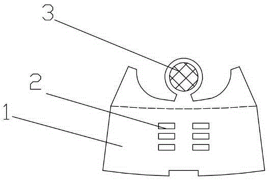
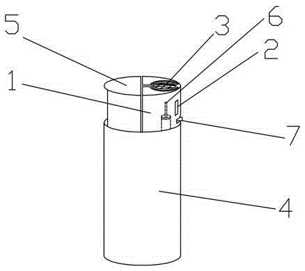
[0007] Embodiment 1: An anti-blocking lighter flame cover, the anti-blocking lighter flame cover is similar in structure to an ordinary lighter flame cover, including a cover body 1, an air inlet hole 2, and an opening 3, and the middle part of the cover body 1 has an air intake Hole 2, there is opening 3 on the top of cover body 1. The anti-blocking lighter flame cover body 1, air intake hole 2, and opening 3 are formed by a whole piece of aluminum alloy plane, and after being folded, a three-dimensional anti-blocking lighter flame cover is formed, which is installed on the lighter. The flame cover of the type lighter is characterized in that a metal mesh is welded in the middle of the opening 3 above the cover body 1, which can prevent sundries from entering the inside of the flame cover. Because the opening 3 above the flame cover body 1 of the anti-blocking lighter is welded with a metal mesh in the middle, debris such as agglomerated clothing fibers etc. are blocked by th...


PUM


Abstract

The invention provides an anti-blocking lighter flame trap that is capable of preventing impurities from going therein to block a lighter valve.

Description

technical field [0001] The invention relates to an anti-blocking lighter flame cover. Background technique [0002] Lighters are common daily necessities. Various lighters currently on the market are usually composed of the following components: a fuselage (containing compressed combustible gas), a lighter, a valve, a valve regulating valve, and a flame cover. Among them, the flame cover is located above the air valve, wrapping the air valve to prevent the flame from being blown out by the wind. The structure of the existing lighter flame cover generally has an air intake hole in the middle of the side of the flame cover body, so that the air circulates and plays a combustion-supporting effect. However, there is a technical problem in the flame cover of the existing lighter: because there is an opening above the flame cover, when the lighter is placed in the pocket or bag for a long time, it is easy to have sundries (such as agglomerated fibers falling off the clothes) En...

Claims


Application Information

Patent Timeline
Patent Type & Authority Applications(China)
IPC IPC(8): F23Q2/50
Inventor 不公告发明人
Owner TIANCHANG EARTHQUAKE OFFICE
Why Eureka
Try Eureka