
Shared oil smoke emission vertical pipe system and control method thereof

A technology of oil fume exhaust and oil fume exhaust fan, which is applied in the field of kitchen oil fume exhaust, and can solve problems such as waste of high-value space

Inactive Publication Date: 2016-02-17
张雄
View PDF8 Cites 12 Cited by
  • Summary
  • Abstract
  • Description
  • Claims
  • Application Information

AI Technical Summary

Problems solved by technology

[0002] The kitchen in the catering industry must be under negative pressure conditions. Generally, the negative pressure value is about 5 to 10pa. Generally, there are multiple catering kitchens, especially in multi-storey hotels or large commercial complexes. Usually, each floor has a separate There is a kitchen, because the interior space of the building is very compact, and there are many kitchen equipment and pipelines, and at the same time, it is limited by height. If the oil fume exhaust treatment is carried out separately for each kitchen in the past, it will often cause waste of high-value space, so usually Centralized fume discharge treatment is adopted from the roof. However, there is no suitable equipment and measures in the market to realize fully automatic and intelligent control of the common fume exhaust pipe method of multiple kitchens.

Method used


Image

  • Shared oil smoke emission vertical pipe system and control method thereof
  • Shared oil smoke emission vertical pipe system and control method thereof
  • Shared oil smoke emission vertical pipe system and control method thereof

Examples


Embodiment Construction

[0031] Below, in conjunction with accompanying drawing and specific embodiment, the present invention is described further:

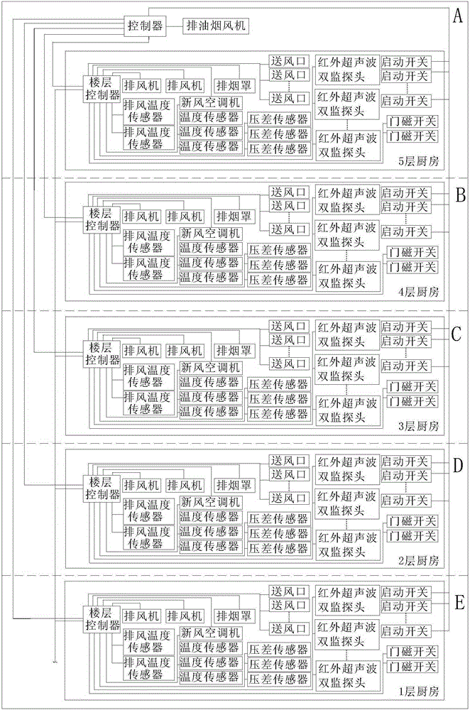
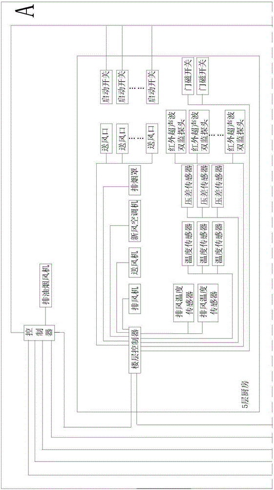
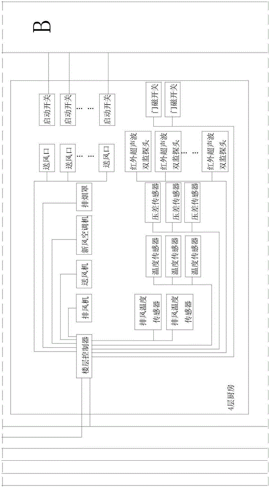
[0032] see figure 1 and figure 2 , the shared oil fume riser system provided by the embodiment of the present invention includes a controller, an oil fume blower, a frequency converter, an oil fume riser, and a plurality of oil fume horizontal pipe assemblies, and the oil fume horizontal pipe assembly includes a valve assembly and an oil fume exhaust pipe assembly. Horizontal Pipe. The oil fume exhaust horizontal pipe in each kitchen includes one or more sections. Among them, in figure 2 In , the oil fume exhaust standpipe is located on the right side of the figure, represented by the thick vertical line connected to the quantitative air valve and the electric valve on the right side of the figure.

[0033] The shared oil fume exhaust riser system of this embodiment can be applied to hotels and large commercial complexes with multiple kitchens. As...


PUM


Abstract

The invention relates to a shared oil smoke emission vertical pipe system and a control method thereof. The shared oil smoke emission vertical pipe system comprises a controller, oil smoke exhausters, frequency convertors, an oil smoke emission vertical pipe and a plurality of oil smoke emission horizontal pipe assemblies. Oil smoke emission horizontal pipes are connected with the oil smoke emission vertical pipe through electric air valves. Starting switches and actuators are all electrically connected with the controller. The electric air valves are connected with one ends of constant air volume valves. The other ends of the constant air volume valves are connected with the oil smoke emission horizontal pipes. The oil smoke exhausters are connected with the controller through the frequency convertors. The starting switches are used for sending starting signals to the controller. The controller is used for controlling the electric air valves to open after receiving the starting signals, and the running air volumes of the oil smoke exhausters are controlled through the frequency convertors. According to the shared oil smoke emission vertical pipe system, the oil smoke emission vertical pipe is shared by the oil smoke emission horizontal pipe assemblies, and through controlling of the controller and the frequency convertors over the oil smoke exhausters, the oil smoke emission requirements for the oil smoke emission vertical pipe shared by the oil smoke emission horizontal pipe assemblies are met, and full-automatic intelligent control is achieved.

Description

technical field [0001] The invention relates to the technical field of kitchen oil fume exhaust, in particular to a shared oil fume exhaust standpipe system and a control method thereof. Background technique [0002] The kitchen in the catering industry must be under negative pressure conditions. Generally, the negative pressure value is about 5 to 10pa. Generally, there are multiple catering kitchens, especially in multi-storey hotels or large commercial complexes. Usually, each floor has a separate There is a kitchen, because the interior space of the building is very compact, and there are many kitchen equipment and pipelines, and at the same time, it is limited by height. If the oil fume exhaust treatment is carried out separately for each kitchen in the past, it will often cause waste of high-value space, so usually Centralized fume discharge treatment is adopted from the roof. However, there is no suitable equipment and measures on the market to realize fully automatic...

Claims


Application Information

Patent Timeline
Patent Type & Authority Applications(China)
IPC IPC(8): F24C15/20
Inventor 张雄
Owner 张雄
Learn More