Turbine pressure relief valve gauge
A technology for pressure relief valves and turbines, which is applied in the field of inspection tools for turbine pressure relief valves. It can solve the problems of low measurement efficiency, long time consumption, and high price of three-coordinate detection instruments, and achieve the effects of improving detection efficiency and avoiding damage or wear.
- Summary
- Abstract
- Description
- Claims
- Application Information
AI Technical Summary
Problems solved by technology
Method used
Image
Examples
Embodiment Construction
[0010] The present invention will be described in further detail below by means of specific embodiments:
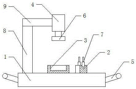
[0011] The reference signs in the drawings of the description include: base 1 , positioning seat 2 , support seat 3 , cylinder 4 , handle 5 , pressure head 6 , go-no-go gauge 7 , pillar 8 , and cantilever 9 .
[0012] The embodiment is basically as attached figure 1 Shown: Turbine pressure relief valve body inspection tool, including base 1, positioning seat 2, support seat 3, cylinder 4. The base 1 is a rectangular stainless steel plate, and the left and right sides of the base 1 are respectively symmetrically fixed with handles 5 made of hard rubber by screws. The left side of the upper end of the base 1 is integrally formed with a vertical pillar 8, and the top of the pillar 8 is fixed with a horizontal cantilever 9 by bolts, and the free end of the cantilever 9 is close to the center of the base 1. The cylinder 4 is fixed on the free end of the cantilever 9, the out...
PUM
 Abstract
Description
Claims
Application Information
 - R&D
- Intellectual Property
- Life Sciences
- Materials
- Tech Scout
- Unparalleled Data Quality
- Higher Quality Content
- 60% Fewer Hallucinations
Browse by: Latest US Patents, China's latest patents, Technical Efficacy Thesaurus, Application Domain, Technology Topic, Popular Technical Reports.
© 2025 PatSnap. All rights reserved.Legal|Privacy policy|Modern Slavery Act Transparency Statement|Sitemap|About US| Contact US: help@patsnap.com

