Detection device used for direct measuring of engine tail gas particulate matter number concentration

A detection device and tail gas particle technology, which is applied in the direction of measurement device, particle suspension analysis, suspension and porous material analysis, etc., to achieve the effect of facilitating flow parameter adjustment

Inactive Publication Date: 2016-02-17
HUAJINHANGWUHANTECH CO LTD
View PDF12 Cites 14 Cited by
  • Summary
  • Abstract
  • Description
  • Claims
  • Application Information

AI Technical Summary

Problems solved by technology

[0005] The purpose of the present invention is to provide a detection device that can directly measure the concentration of engine exhaust particulate matter, so as to solve the technical problem that the existing device needs to add volatile substance removal equipment to accurately measure. The device can accurately count solid particles, And effectively reduce the complexity and detection cost of the detection device

Method used


Image

  • Detection device used for direct measuring of engine tail gas particulate matter number concentration
  • Detection device used for direct measuring of engine tail gas particulate matter number concentration

Examples


Embodiment 1

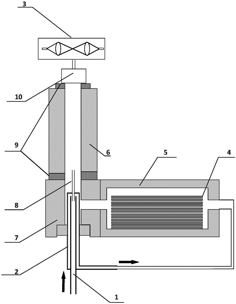
[0023] The detection device for measuring the number concentration of engine exhaust particulate matter, its structure schematic diagram is as follows figure 1 As shown, it includes an intake pipe 1, a capillary tube 8, a connecting pipe 2, a saturator 5, a condenser 6, an intermediate connecting piece 7, a mixing chamber 10, an optical particle counter 3 and a diesel particulate filter 4, wherein one end of the connecting pipe 2 Connect the intermediate connecting piece 7, one end of the connecting pipe 7 is inserted into the intermediate connecting piece 7, but not communicated with the connecting piece, at this end, the air inlet pipe 1 is inserted into the connecting pipe 2, and one end of the air inlet pipe 1 is provided with a capillary 8, The capillary 8 passes through the connecting pipe, and the length of the capillary 8 can reach the condenser, that is, the capillary 8 communicates with the condenser 6, and the other end of the connecting pipe 2 communicates with the ...

Embodiment 2

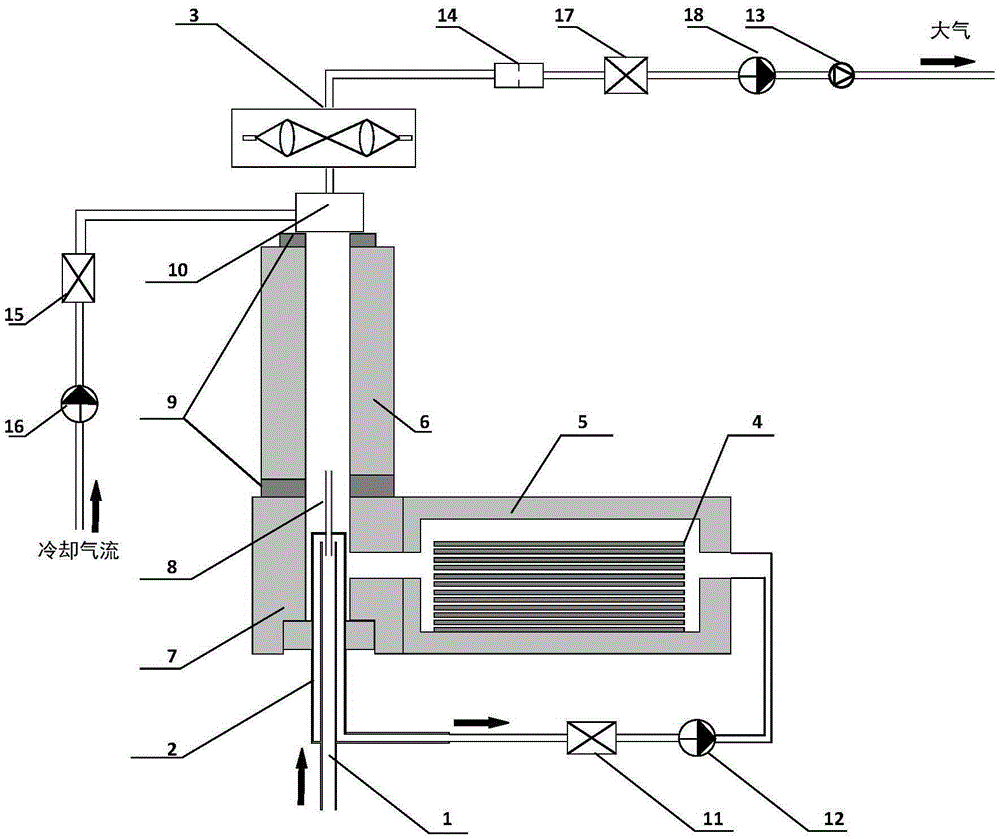
[0032] On the basis of Example 1, in order to make a part of the detected gas into clean air so that it serves as sheath gas, a first high-efficiency filter is set in the connecting pipe; in order to effectively control the airflow into the device for detection, in The connecting pipe is provided with a first rotameter. The first rotameter can be arranged on the connecting pipe connected to the saturator after the first high-efficiency filter.

[0033] In order to reduce the temperature of the gas outlet from the condenser, so as to ensure that the outlet airflow does not damage the photoelectric unit, an inlet is set at the other end of the mixing chamber, and the front end of the inlet is connected to a second high-efficiency filter to provide clean airflow for it at the same time. airflow. The second high-efficiency filter and the mixing chamber can be connected by pipelines; in order to effectively control the diluent gas flow rate to select suitable working conditions to...


PUM


Abstract

The invention discloses a detection device used for direct measuring of engine tail gas particulate matter number concentration. The detection device comprises an air inlet pipe, a capillary, a connecting pipe, a saturator, a condenser, a middle connecting part, a mixing chamber, an optical particle counter, and a diesel engine particulate matter filter; one end of the connecting pipe is inserted into the middle connecting part, and the air inlet pipe is sleeved with the same end of the connecting pipe; the top part of the air inlet pipe is connected with the capillary; the capillary is inserted into the condenser; the other end of the connecting pipe is communicated with the saturator; the middle connecting part is communicated with the condenser, and is communicated with the saturator; the upper end of the condenser is connected with the mixing chamber; the optical particle counter is connected with the mixing chamber; and the diesel engine particulate matter filter is arranged in the saturator. According to the detection device, influence of volatile substance in engine tail gas is avoided in a simple mode; only solid particulate matter number concentration is detected; and detection cost is reduced.

Description

technical field [0001] The invention relates to the field of environmental monitoring equipment, in particular to a detection device for directly measuring the number concentration of engine exhaust particles. Background technique [0002] Particulate matter emitted by motor vehicles is an important source of particulate matter in the atmospheric environment. The number concentration of engine exhaust particulate matter has a three-peak distribution according to particle size, nucleated particles (<50nm), aggregated particles (50nm—500nm), and coarse particles (>500nm). In the engine exhaust, the mass of nucleated particles only accounts for 0.1%-10% of the particle mass, but accounts for 90% of the total number. Although the mass weight of nucleated particles is low, they account for the majority of the total particle number. Particles mainly detects the number of nucleated particles. And studies have shown that compared with large particles, fine particles are more...

Claims


Application Information

Patent Timeline
Patent Type & Authority Applications(China)
IPC IPC(8): G01N15/06
Inventor 陈龙飞张鑫郭跃杰马越岗张萃琦
Owner HUAJINHANGWUHANTECH CO LTD
Why Eureka
Try Eureka