Cable partial discharge concentration point detection method and system

A partial discharge and detection method technology, applied in the direction of testing dielectric strength, etc., can solve the problems of little technology accumulation, difficulty in large-scale popularization and application, and unsuitability for large-scale data processing, so as to solve inaccuracies and mistakes and reduce manpower , cost reduction effect

Active Publication Date: 2016-02-17
YUNNAN POWER GRID CO LTD KUNMING POWER SUPPLY BUREAU
View PDF2 Cites 4 Cited by
  • Summary
  • Abstract
  • Description
  • Claims
  • Application Information

AI Technical Summary

Problems solved by technology

[0003] However, on the whole, there are still relatively few domestic and foreign product and technology accumulations for the application of oscillatory waves in cable fault detection and location.
[0004] At present, the main application of oscillatory wave detection technology is to carry out the research on the detection and location of cable insulation defects, which is to manually judge whether there is a discharge concentration point on the partial discharge signal detected under the oscillatory voltage, which brings the following shortcomings: 1. Manual judgment requires expert experience , it is difficult to popularize and apply on a large scale; 2. The efficiency of manual judgment is low, which is not suitable for large-scale data processing; 3. Manual judgment cannot be well adapted to the intelligent processing of partial discharge detection

Method used


Image

  • Cable partial discharge concentration point detection method and system
  • Cable partial discharge concentration point detection method and system
  • Cable partial discharge concentration point detection method and system

Examples


Embodiment Construction

[0025] In order to make the object, technical solution and advantages of the present invention clearer, the present invention will be further described in detail below in conjunction with the accompanying drawings and embodiments. It should be understood that the specific embodiments described here are only used to explain the present invention, and do not limit the protection scope of the present invention.

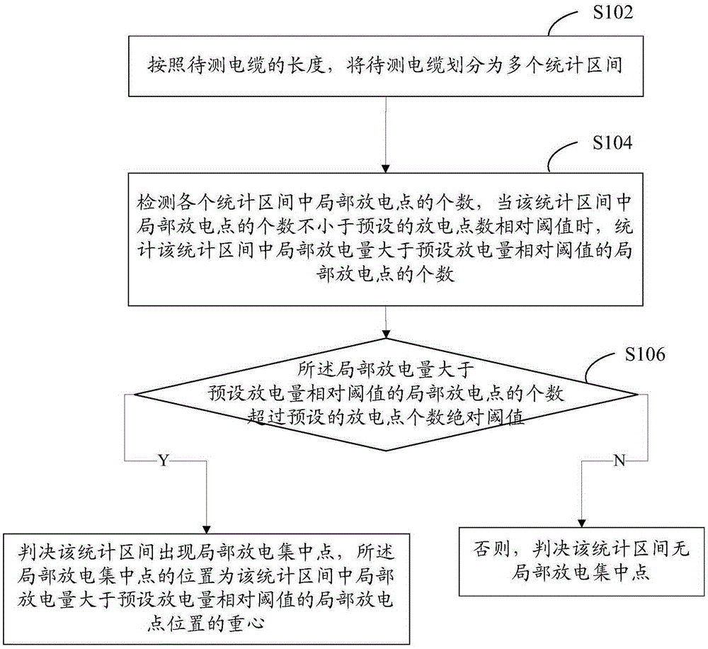
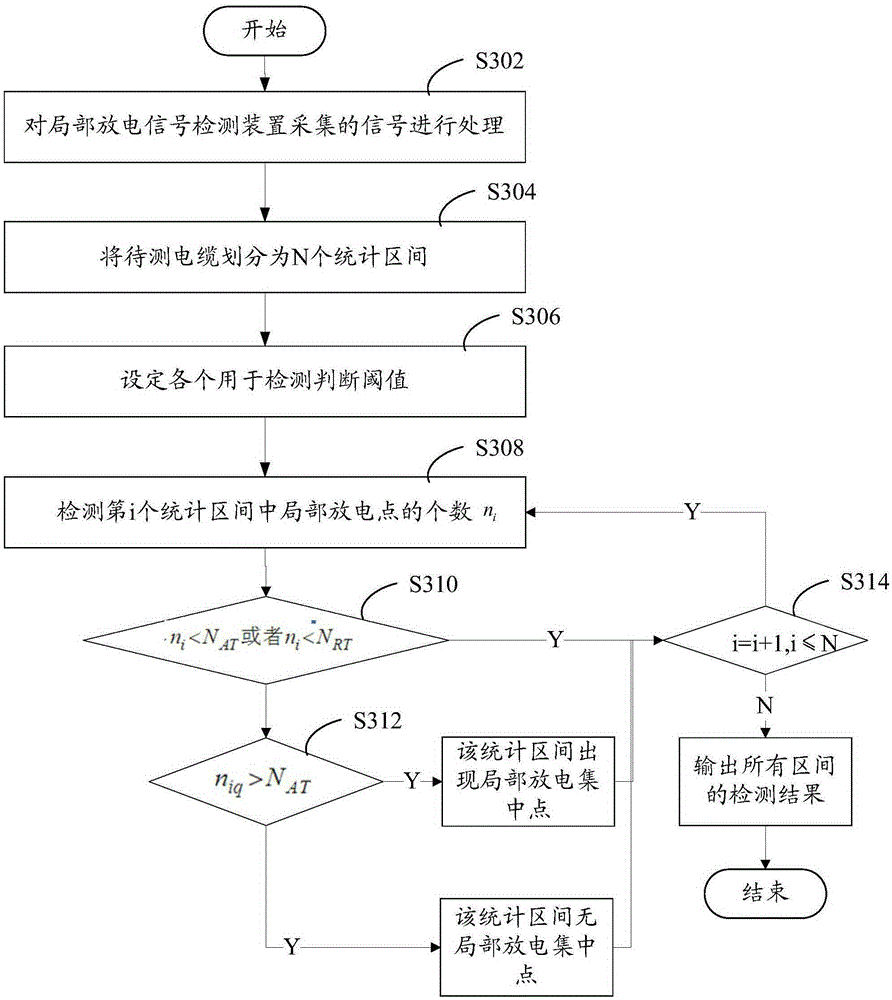
[0026] figure 1 The flow chart of the method for detecting concentrated points of cable partial discharge in an embodiment of the present invention is shown in FIG.

[0027] The method for detecting concentrated points of cable partial discharge comprises the following steps:

[0028] S102, divide the cable to be tested into a plurality of statistical intervals according to the length of the cable to be tested;

[0029] S104. Detect the number of partial discharge points in each statistical interval. When the number of partial discharge points in the statistical interv...


PUM


Abstract

The invention provides a cable partial discharge concentration point detection method and system. The cable partial discharge concentration point detection method comprises the following steps: dividing a cable to be detected into a plurality of statistical intervals; if the quantity of partial discharge points in the statistical intervals is no less than a pre-set relative threshold value of the quantity of the discharge points, counting up the quantity of the partial discharge points with the partial discharge amount, which is greater than a relative threshold value of a pre-set discharge amount, in the statistical intervals; when the quantity of the partial discharge points with the partial discharge amount, which is greater than the relative threshold value of the pre-set discharge amount, is more than an absolute threshold value of the pre-set quantity of the discharge points, judging partial discharge concentration points in the statistical intervals and acquiring that the positions of the partial discharge concentration points are gravity centers of the positions of the partial discharge points with the partial discharge amount, which is greater than the relative threshold value of the pre-set discharge amount; otherwise, judging that the statistical intervals have no partial discharge concentration points. The cable partial discharge concentration point detection method and system can be used for automatically and accurately judging and positioning the positions of the partial discharge concentration points on the cable to be detected and the accuracy problem of the detection of the partial discharge concentration points can be effectively solved.

Description

technical field [0001] The invention relates to the technical field of partial discharge detection, in particular to a method for detecting concentrated points of partial discharge in cables and a detection system for concentrated points of partial discharge in cables. Background technique [0002] With the increasing expansion of the power grid and the longer running time of cables, defects such as insulation and aging of cables will occur, accompanied by partial discharge, which will cause potential safety hazards to the power system. Partial discharge detection is one of the most effective methods to quantitatively analyze the degree of insulation aging. OWTS oscillating wave partial discharge detection and location technology is an emerging new technology for cable partial discharge diagnosis in the world in recent years. Relevant studies have shown that the partial discharge detection and location results under OWTS oscillatory wave voltage and 50HZ power frequency AC ...

Claims


Application Information

Patent Timeline
Patent Type & Authority Applications(China)
IPC IPC(8): G01R31/12
Inventor 鲁源袁峻韦瑞峰龙红星董伟徐肖庆赵荣普周懋坤刘宗兵陈井锐赵灿辉荀羽
Owner YUNNAN POWER GRID CO LTD KUNMING POWER SUPPLY BUREAU
Why Eureka
Try Eureka