
Projection system

A technology of projection system and lighting optical system, which is applied in the fields of optics, instruments, color TV components, etc., and can solve the problems of limited application of local dimming technology

Active Publication Date: 2016-02-17
OSRAM GMBH
View PDF5 Cites 29 Cited by
  • Summary
  • Abstract
  • Description
  • Claims
  • Application Information

AI Technical Summary

Problems solved by technology

However, in projection systems (such as projectors), the application of local dimming technology is still very limited

Method used


Image

  • Projection system
  • Projection system
  • Projection system

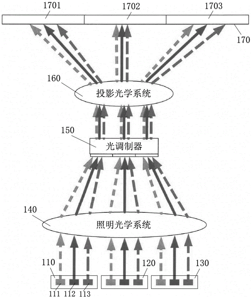
Examples


Embodiment Construction

[0023] Hereinafter, a projector will be taken as an example to describe the projection system according to the present invention. However, it should be understood that the present invention is not limited to projectors, but includes all devices or systems involving the use of projection technology.

[0024] Typically, a projector's backlight has not just one light-emitting surface, but many light-emitting surfaces. The number of light-emitting surfaces can be divided into groups, so the backlight can include multiple groups of light-emitting surfaces. Each light-emitting surface group includes multiple light-emitting surfaces, and the multiple light-emitting surfaces are usually arranged in an array, such as a matrix-like manner. In some cases, the light-emitting surface can be realized by light-emitting diodes (LEDs), and the backlight can include multiple LED arrays, each LED array is composed of multiple LEDs, and each LED array corresponds to a certain LED on the light mo...


PUM


Abstract

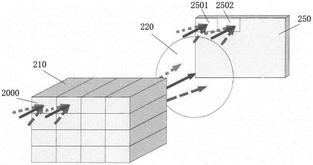
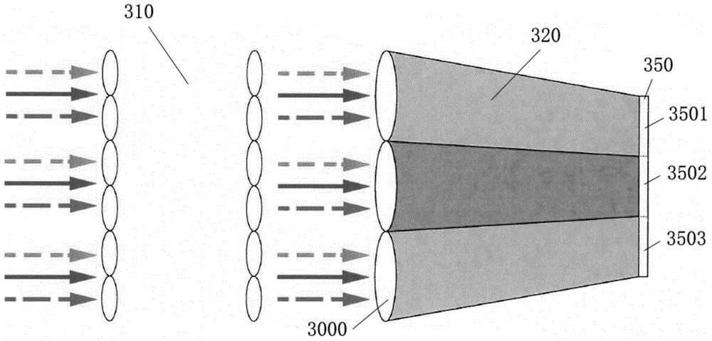
The invention provides a projection system, which comprises at least two light-emitting surface groups, a light modulator, an illuminating optical system and a light source controller, wherein each light-emitting surface group comprises a plurality of light-emitting surfaces of emitting different colors; the illuminating optical system is arranged between the at least two light-emitting surface groups and the light modulator; the illuminating optical system comprises at least two light paths which correspond to the at least two light-emitting surface groups respectively; light emitted from each light-emitting surface group evenly irradiates a specific input region of the light modulator through the corresponding light path; and the light source controller adjusts the illuminating brightness and / or color ratio on the corresponding input region of the light modulator by individually controlling at least one of the light-emitting surface groups.

Description

technical field [0001] The present invention relates to a projection system, in particular, to a projection system capable of realizing local dimming and uniform illumination. Background technique [0002] Currently, local dimming technology has been widely used in flat panel displays (eg, LCD TVs) to reduce power consumption of backlight sources. However, in projection systems (such as projectors), the application of local dimming technology is still very limited. [0003] Local dimming technology refers to adjusting the backlight according to the brightness and darkness of the displayed image, so that the brightness of the bright area in the displayed image can reach the maximum, while the brightness of the dark area can be reduced, or even turn off the backlight corresponding to the dark area. . This achieves optimum image contrast and at the same time reduces the power consumption of the backlight. [0004] In addition, in a projection system, it is a basic performanc...

Claims


Application Information

Patent Timeline
Patent Type & Authority Applications(China)
IPC IPC(8): G03B21/20G03B21/14
CPCG03B21/005G03B21/2053H04N9/3155H04N9/3164H04N9/3182
Inventor 丁毅毛峻伟康庆
Owner OSRAM GMBH
Learn More