An optical communication energy-saving control method and optical communication equipment

A light-emitting control signal and optical communication technology, which is applied in the field of optical communication, can solve the problems of low energy-saving control efficiency of optical modules, and achieve the effects of improving energy-saving control efficiency, increasing service life, and simple control methods

Active Publication Date: 2018-01-02
西安无限光通讯有限公司
View PDF5 Cites 0 Cited by
  • Summary
  • Abstract
  • Description
  • Claims
  • Application Information

AI Technical Summary

Problems solved by technology

The lack of these existing technologies leads to low energy-saving control efficiency of optical modules

Method used


Image

  • An optical communication energy-saving control method and optical communication equipment
  • An optical communication energy-saving control method and optical communication equipment
  • An optical communication energy-saving control method and optical communication equipment

Examples


Embodiment Construction

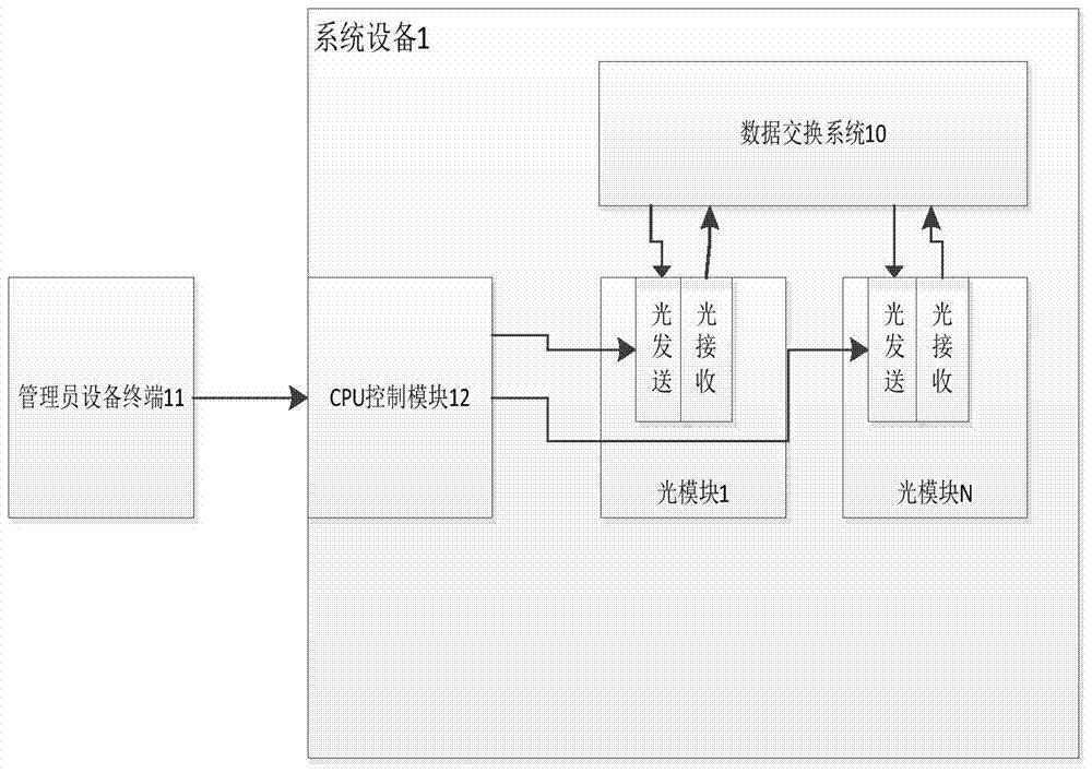
[0025] In order to more clearly illustrate the embodiments of the present invention or the technical solutions in the prior art, the specific implementation manners of the present invention will be described below with reference to the accompanying drawings. Obviously, the accompanying drawings in the following description are only some embodiments of the present invention, and those skilled in the art can obtain other accompanying drawings based on these drawings and obtain other implementations.

[0026] In order to make the drawing concise, each drawing only schematically shows the parts related to the present invention, and they do not represent the actual structure of the product. In addition, to make the drawings concise and easy to understand, in some drawings, only one of the components having the same structure or function is schematically shown, or only one of them is marked. Herein, "a" not only means "only one", but also means "more than one".

[0027] figure 2...


PUM


Abstract

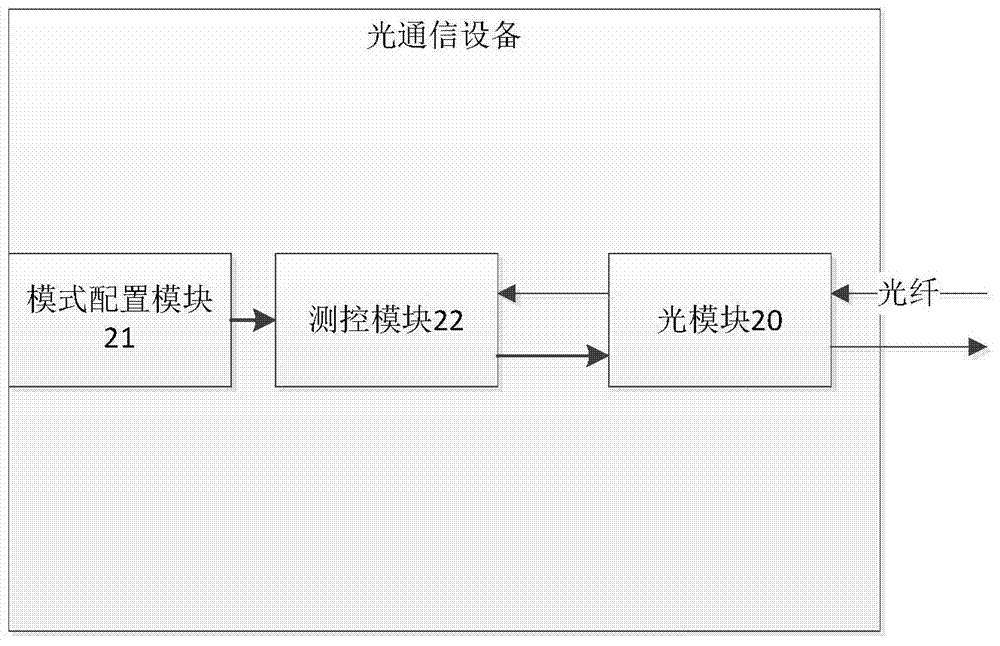
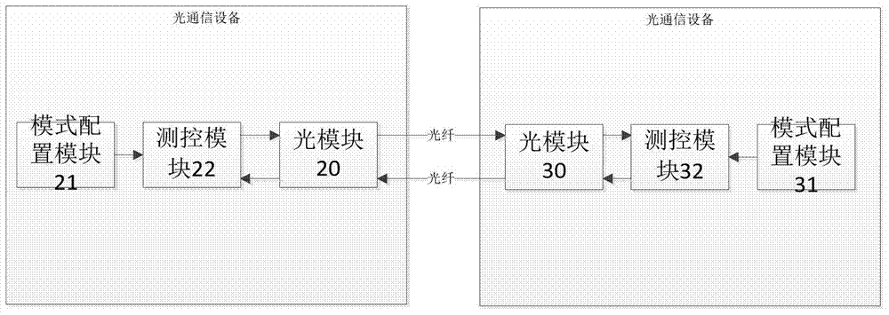
The invention discloses an optical communication device and an optical communication energy-saving control method applied for the same. The optical communication device comprises an optical module, a mode configuration module and a measurement and control module. The configuration module is used for generating mode instructions so as to configure the working modes of the optical module. The measurement and control module can carry out comprehensive judgment according to optical signals received by the optical module and the mode instructions and carry out intelligent management and control on on / off of a sending unit of the optical module, thereby achieving the energy-saving objective of the optical module and extending service lifetime of the optical module.

Description

technical field [0001] The invention relates to the technical field of optical communication, in particular to an optical communication device and an optical communication energy saving method applied to the device. Background technique [0002] Optical Communication is a communication method that uses light waves as information carriers and optical fibers as transmission media. Its communication principle is: at the sending end, the transmitted information should first be converted into an electrical signal, and then modulated onto the polar beam emitted by the laser, so that the intensity of the light changes with the amplitude (frequency) of the electrical signal, and passes through the optical fiber through the optical signal. The principle of total reflection transmits; at the receiving end, the detector receives the optical signal and converts it into an electrical signal, and restores the original information after demodulation. With the significant reduction in the ...

Claims


Application Information

Patent Timeline
Patent Type & Authority Patents(China)
IPC IPC(8): H04B10/075
CPCH04B10/075
Inventor 吴夕周
Owner 西安无限光通讯有限公司
Why Eureka
Try Eureka