Eureka AIR delivers breakthrough ideas for toughest innovation challenges, trusted by R&D personnel around the world.

Lighting systems and methods providing active glare control

A lighting system and glare technology, applied in lighting devices, energy-saving control technology, light sources, etc., can solve the problems of observers' glare and being in the middle of the observer's field of view, etc.

Active Publication Date: 2016-02-17
GE LIGHTING SOLUTIONS LLC
View PDF4 Cites 8 Cited by
  • Summary
  • Abstract
  • Description
  • Claims
  • Application Information

AI Technical Summary

Problems solved by technology

[0004] Luminaires that direct high-angle light primarily downward may not present glare to observers who are not looking directly up at the luminaire, but such luminaires may illuminate only a small area
Other luminaires that direct light at high or low angles can illuminate a larger area, but can present glare to distant observers
In some cases, the observer must look at objects near the light source so that light from the source may be in the observer's field of view

Method used


Image

  • Lighting systems and methods providing active glare control
  • Lighting systems and methods providing active glare control
  • Lighting systems and methods providing active glare control

Examples


Embodiment Construction

[0025] The present disclosure can be understood by reference to the following detailed description taken in conjunction with the accompanying drawings briefly described below. It is to be noted that for clarity of illustration, some elements in the figures may not have been drawn to scale.

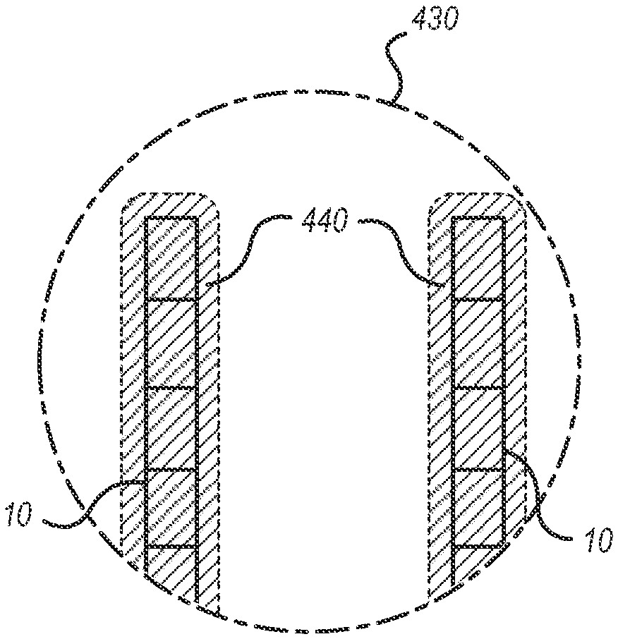
[0026] figure 1 The schematic diagram illustrates a range-activated luminaire 100 in an embodiment that provides active glare control. Luminaire 100 includes a dimmable light source 110 and a range finder 120 . The dimmable light source 110 illuminates the active volume terminated at the support surface 40 in the vicinity. Such as figure 1 As shown, the dimmable light source 110 illuminates the volume between the dashed lines A and A' terminating at the support surface 40 . figure 1 Inside, a forklift 20 carrying objects 30 loaded into storage racks 10 is located within the active volume. Light 112 from light source 110 is generally at an angle irradiance 132 between dashed lines A...


PUM


Abstract

A light fixture includes a dimmable light source that emits light downwardly, and a downward-looking rangefinder proximate and operatively coupled with the light source. When the rangefinder detects an object at a measured height that exceeds a first threshold, the light source dims according to the measured height. A light fixture that provides illumination with active glare control for a lighted area includes one or more first light sources that emit high-angle light, and one or more dimmable second light sources that emit low-angle light, into the lighted area. The system also includes a camera that captures images of the lighted area, and a controller that is (a) operable to identify one or more activity locations within the lighted area from the images, and (b) operatively coupled to dim one or more of the light sources that illuminate the one or more activity locations.

Description

[0001] related application [0002] This application claims priority benefit of US Provisional Patent Application Serial No. 61 / 815715, filed April 24, 2013, and Serial No. 14 / 259778, filed April 23, 2014, which are hereby incorporated by reference. Background technique [0003] Glare is a common problem in nature and in many lighting situations. Sometimes glare is the result of the physical proximity of a light source to the object being viewed. Other times, the light source is not physically close to the object, but behind it so that the source is in the same field of view as the object with respect to the observer. Humans and certain animals have facial shapes and features such as eyebrows that form a natural glare shield so that high angle light (light forming a high angle relative to the horizontal) is not visually objectionable. For example, the effect of glare is easily observed outdoors during the early or late hours of a sunny day. When the observer or photographer...

Claims


Application Information

Patent Timeline
IPC IPC(8): H05B33/08H05B37/02H05B44/00
CPCH05B47/175H05B47/125H05B45/10Y02B20/40
Inventor N.P.肯农J.比斯伯格J.朗布克
Owner GE LIGHTING SOLUTIONS LLC
Why Eureka
Eureka Blog
Learn More