
Foldable foot supporting device

A footrest and footpad technology, applied in the field of foldable footrest devices, can solve the problems of simplicity, poor stability and strength, and poor resting effect, and achieve the effects of strong stability, compact structure, comfortable and good resting posture

Active Publication Date: 2016-02-24
盐城汇达生物科技有限公司
View PDF6 Cites 12 Cited by
  • Summary
  • Abstract
  • Description
  • Claims
  • Application Information

AI Technical Summary

Problems solved by technology

[0003] The technical purpose of the present invention is to provide a foldable foot rest device, which solves the problems of crudeness, poor stability and strength, and poor rest effect on the traditional seat mechanism

Method used


Image

  • Foldable foot supporting device
  • Foldable foot supporting device
  • Foldable foot supporting device

Examples


Embodiment 1

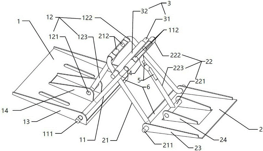
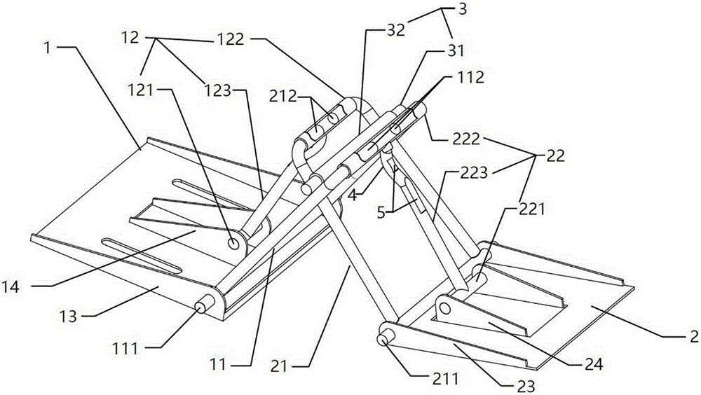
[0040] Embodiment one: see figure 1 , Figure 5 , Image 6 , Figure 7 , Figure 8 , Figure 9 , an embodiment of a foldable footrest device, including a seat connection base 1, a foot pad connection base 2, a first swing frame 11, a second swing frame 21, and a seat connection base 1 and a second swing frame respectively. The hinged first bracket 12 of the swing frame 21 and the second bracket 22 hinged with the foot pad connection base 2 and the first swing frame 11 respectively, the seat connection base 1 and the foot pad connection base 2 can be selected as connecting plates, The foot pad is connected to the base 2 and the cloth pad is connected, and the footrest device is stretched or folded through the first swing frame 11, the second swing frame 21, the first bracket 12 and the second bracket 22 to connect the seat connection base to the foot pad. The base is located on the same plane or stacked up and down; the first swing frame 11 has a first swing frame rear sha...

Embodiment 2

[0046] Embodiment two: see figure 2 , The main difference between this embodiment and the foregoing embodiments is that the first swing frame rear shaft 111 and the second swing frame rear shaft 211 are both integrated shafts, which have higher structural strength and are easier to process.

Embodiment 3

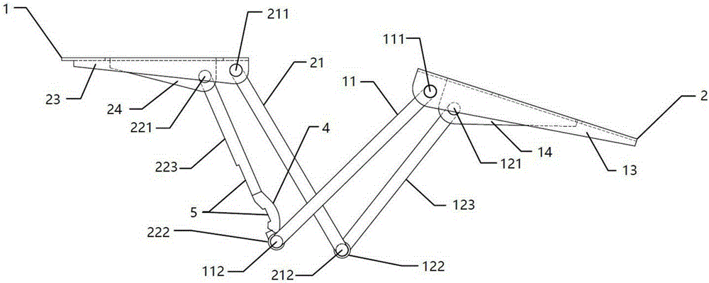
[0047] Embodiment three: see image 3 , the main difference between this embodiment and the previous embodiments is that there is no limit mechanism, and the second linkage rod 223 (or the first linkage rod 123) is provided with a bending convex part 4, through the bending convex part 4 and the first A linkage rod 123 (or the second linkage rod 223) conflicts to limit the relative position of the first linkage rod 123 and the second linkage rod 223, as image 3 As shown; of course, another way can also be selected, that is, the first linkage rod 123 and the second linkage rod 223 are provided with a bending protrusion 4, and the first linkage rod 123 and the second linkage rod 123 are limited by the mutual interference of the bending protrusion 4. The relative positions of the two linkage rods 223.


PUM


Abstract

A foldable foot supporting device comprises a chair seat connecting base, a foot pad connecting base, a first swing frame, a second swing frame, a first support connected with the chair seat connecting base and the second swing frame in a hinged mode and a second support connected with the foot pad connecting base and the first swing frame. The chair seat connecting base and the foot pad connecting base of the foot supporting device are located in a same plane or vertically overlapped through stretching or folding of the first swing frame, the second swing frame, the first support and the second support. According to the foldable foot supporting device, the structure is compact, use is convenient, and people can put the legs and the feet on the device to have a comfortable and good rest posture to relieve fatigue. The foldable foot supporting device can quickly and conveniently achieve the stretching and folding functions and is higher in structural strength and stability, smaller in occupied space after being stored, excellent in practicability and very suitable for being used and popularized.

Description

technical field [0001] The invention relates to the technical field of leisure equipment, in particular to a foldable footrest device. Background technique [0002] Seats are one of the most common and most commonly used rest tools. In order to relieve fatigue, people often sit directly on chairs and rest at their desks. Sometimes they feel very uncomfortable, and improper rest postures for a long time will also cause adverse health effects on people. influences. Although there are various types of office, home, and public leisure seats designed on the market, such as reclining chairs, rocking chairs, etc., to help people obtain a comfortable and good rest effect, without any auxiliary rest device, they still feel that the lower body and legs are placed Inconvenience, feeling sick. A leisure chair with a footrest disclosed in a patent document whose authorization notification number is CN204218418U includes an underframe, the underframe includes a front sill, and a footres...

Claims


Application Information

Patent Timeline
Patent Type & Authority Applications(China)
IPC IPC(8): A47C7/52
CPCA47C7/52
Inventor 丁亮
Owner 盐城汇达生物科技有限公司
Learn More