Pin bending fixture for CQFJ product

A product and pin technology, which is applied in the field of pin bending fixtures, can solve the problems of left and right asymmetry of finished products, unsightly work efficiency, etc., and achieve the effect of reducing requirements, improving work efficiency, and facilitating pin bending

Inactive Publication Date: 2016-02-24
FUJIAN MINHANG ELECTRONICS
View PDF8 Cites 2 Cited by
  • Summary
  • Abstract
  • Description
  • Claims
  • Application Information

AI Technical Summary

Problems solved by technology

[0002] Before the existing CQFJ product is finished, the long line of its pin needs to be shortened. There are four rows of pins on the four sides of the CQFJ product. The feet are bent, and the bending process still relies on manual tools to bend the pins of the CQFJ product in turn. The finished product will be asymmetrical from left to right, which is not beautiful and has low work efficiency.

Method used


Image

  • Pin bending fixture for CQFJ product

Examples


Embodiment Construction

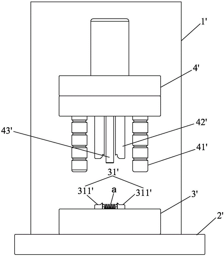
[0009] Such as figure 1 As shown, the pin bending fixture used for CQFJ products of the present invention includes a frame 1 ', a horizontal workbench 2' installed on the frame 1', a lower mold 3' placed on the workbench, and a lower mold 3' above the upper mold 4' that slides up and down along the frame 1' and the transmission device (not shown) that drives the upper mold. The upper mold 4' is provided with four guide posts 41' and four punches. 42' and a movable thimble 43', the movable thimble 43' is set at the center of the upper mold 4', the four punches 42' form a quadrilateral around the movable thimble 43', the four The guide post 41' surrounds the movable thimble 43' and is located outside the punch 42'. The lower mold 3' is provided with a movable stopper mechanism 31', and the movable stopper mechanism 31' is located on the Below the punch 42', the movable stop mechanism 31' is used to fix the CQFJ product a, and make the punch 42' directly above the pin of the CQF...


PUM


Abstract

The invention provides a pin bending fixture for a CQFJ product. The pin bending fixture comprises a rack, a horizontal working table mounted on the rack, a lower die arranged on the working table, an upper die which slides up and down above the lower die along the rack, and a transmission device used for driving the upper die, wherein four guide pillars, four punches and a movable ejector pin are arranged on the upper die; the movable ejector pin is arranged in the center of the upper die; the four punches surround the movable ejector pin to form a quadrangle; the four guide pillars surround the movable ejector pin, and are positioned on the outer sides of the punches; a movable material stopping mechanism is arranged on the lower die; and the movable material stopping mechanism is positioned below the punches, and is used for fixing the CQFJ product, so as to enable the punches to be positioned right above the pin of the CQFJ product. According to the pin bending fixture, the working efficiency of workers is improved, and the requirement on workers is reduced.

Description

technical field [0001] The invention relates to a pin bending jig for CQFJ products. Background technique [0002] Before the existing CQFJ product is finished, the long line of its pin needs to be shortened. There are four rows of pins on the four sides of the CQFJ product. The pins are bent, and the bending process still relies on manual use of tools to bend the pins of the CQFJ product in turn. The finished product will be asymmetrical from left to right, which is not beautiful and has low work efficiency. Contents of the invention [0003] The technical problem to be solved by the present invention is to provide a pin bending jig for CQFJ products, which reduces the reject rate and improves the aesthetics of CQFJ products. [0004] The present invention is achieved in this way: a pin bending fixture for CQFJ products, including a frame, a horizontal workbench installed on the frame, a lower mold placed on the workbench, and a An upper mold that slides up and down and...

Claims


Application Information

Patent Timeline
Patent Type & Authority Applications(China)
IPC IPC(8): B21F1/00
CPCB21F1/004
Inventor 余咏梅周丽华张南菊
Owner FUJIAN MINHANG ELECTRONICS
Why Eureka
Try Eureka