Uniform mixing and stirring device for livestock feed processing
A technology of uniform mixing and stirring device, which is applied to mixers, feeds, mixers and other directions with rotating stirring devices, can solve problems such as insufficient uniformity and inability to mix and deploy at the same time, and achieve the effect of improving work efficiency.
- Summary
- Abstract
- Description
- Claims
- Application Information
AI Technical Summary
Problems solved by technology
Method used
Image
Examples
Embodiment 1
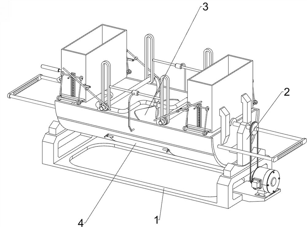
[0025]Such asfigure 1 As shown, a uniform mixing stirring device for animal husbandry processing, including a bottom plate 1, a stirring mechanism 3, and a picking mechanism 4, and both sides of the bottom plate 1 are provided with a first bearing housing 2, and the bottom plate 1 is provided with a stirring mechanism 3. , A feed mechanism 4 is provided on the side of the stirring mechanism 3.
[0026]During the mixing stirring of livestock feed, the raw materials were uniformly mixed by the stirring mechanism 3 in the box, and then the opening and closing of the discharge port is achieved by the picking mechanism 4, and the mixture falls from the outlet under the conduction of the 3 force of the stirring mechanism. , Complete the mixing stirring process for feed processing.
Embodiment 2
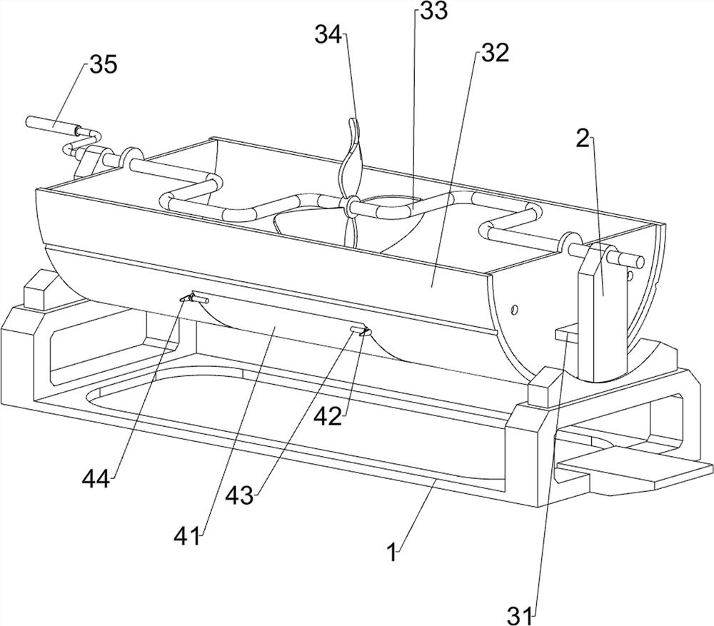
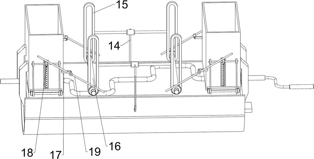
[0028]Such asfigure 2 withimage 3 As shown, the stirring mechanism 3 includes a first fixing block 31, a frame 32, a shaped rod 33, a mixing blade 34, and a first handle 35, and a medium in the middle of the two first bearing housing 2. The first fixing block 31 is provided, and there is a casing 32 between the two first fastening blocks 31, and the two first bearing housing 2 is rotated, and the shaped rod 33 is provided, and the shaped rod 33 is provided with stirring blades 34; One handle 35, one end of the shaped rod 33 is provided with a first handle 35.
[0029]The picking mechanism 4 includes a first baffle 41, a guide sleeve 42, a first slider 43, and a second handle 44. The lower part of the casing 32 is opened, and the square hole is rotated by the shaft pin. A stopper 41, the casing 32 is configured with two guiding sleeve 42, and the guide sleeve 42 is provided with the first slider 43, and the first slider 43 is located at one end of the first baffle 41. Second handle 44.
[...
Embodiment 3
[0032]Such asFigure 4 withFigure 5As shown, on the basis of Example 2, a support plate 5, a lower binder, a second baffle 7, a first rotating shaft 8, a link 9, a first slot plate 10, a slider 11, The second shaft 12 and the elastic member 13, and the frame 32 is provided with the support plate 5 on both sides of the first housing 2, and the upper portion of the support plate 5 is provided on the upper side of the support plate 5. The aperture, the second baffle 7 passes through the rectangular via sliding in the bottom of the lower casing 6, and the second baffle 7 is provided with a first axle 8, and the first spindle 8 is symmetrically configured with two links 9. The lower tank 6 is disposed in the middle of the first shaft 8 side, and the first slide plate 10 is slidably disposed with a slider 11, and there is a through hole in the center of the slider 11, and in the vias The second axis 12 is provided, and the second rotating shaft 12 is hinged from the two links 9, and the el...
PUM
 Abstract
Description
Claims
Application Information
 - R&D
- Intellectual Property
- Life Sciences
- Materials
- Tech Scout
- Unparalleled Data Quality
- Higher Quality Content
- 60% Fewer Hallucinations
Browse by: Latest US Patents, China's latest patents, Technical Efficacy Thesaurus, Application Domain, Technology Topic, Popular Technical Reports.
© 2025 PatSnap. All rights reserved.Legal|Privacy policy|Modern Slavery Act Transparency Statement|Sitemap|About US| Contact US: help@patsnap.com


