Gas shield clamping machine

A gas protection, clamping machine technology, applied in the direction of the chuck, the manipulator, the program control manipulator, etc., can solve the problems of high production and use cost, low work efficiency, insufficient safety, etc., and achieves low production cost, simple structure, easy to use. effect of operation

Inactive Publication Date: 2013-07-10
FIVE POWER ELECTRICAL TECHKUNSHAN
View PDF0 Cites 0 Cited by
  • Summary
  • Abstract
  • Description
  • Claims
  • Application Information

AI Technical Summary

Problems solved by technology

[0002] In the process of processing cylindrical workpieces, clamping is required, and the traditional clamping method is manual operation. On the one hand, this method is not safe enough, and on the other hand, the work efficiency is low. Even if the clamping machine is used, the machine itself It is also very complicated, and the production and use costs are very high

Method used


Image

  • Gas shield clamping machine
  • Gas shield clamping machine

Examples


specific Embodiment approach

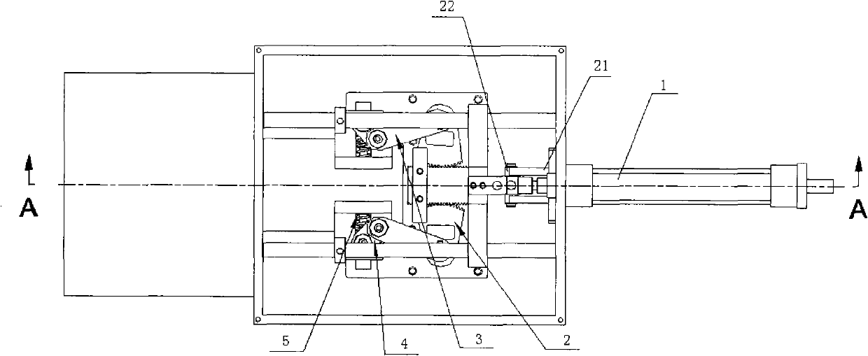
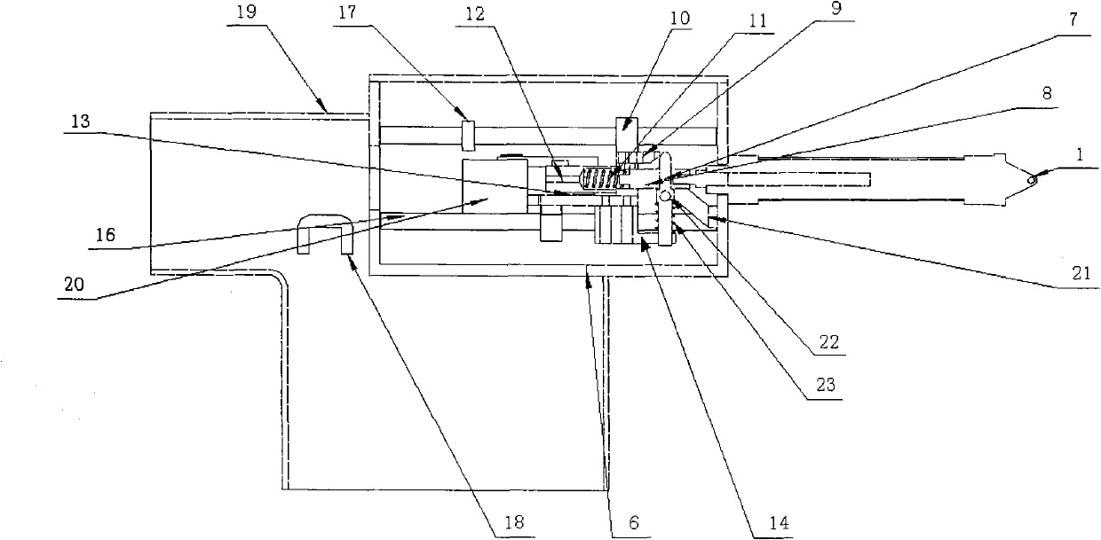
[0021] figure 1 It is a top view of an embodiment of the present invention; figure 2 for figure 1 A view from direction A.

[0022] Such as figure 1 and figure 2 Shown:

[0023] The gas-protected clamping machine includes a box body 6 with openings on the front and lower parts, a gripper 20 arranged in the box body 6, a sector gear 2, a rack 12, a rack seat 10, a flat plate 13, a joint 8, The hanging rod 7 and the cylinder 1 arranged at the rear of the box body, wherein the piston at the front of the cylinder 1 is connected to the joint 6, the through hole in the middle of the joint 6 is inserted with the hanging rod 7, and the hanging rod 7 located at the bottom of the joint 8 Also interspersed with a hanging rod shaft 22 in the through hole, the hanging rod shaft 22 cooperates with the positioning plate 21 arranged on the rear portion of the casing 6, and the top of the rack seat 10 is provided with a hanging plate 9 that matches the hanging rod 7, and the hanging Th...


PUM


Abstract

The invention discloses a gas shield clamping machine which comprises a cabinet, a clamp, a quadrant gear, a rack, a rack seat, a flat plate, a joint, a hang lever and a gas cylinder, wherein the piston at the front part of the gas cylinder is connected with the joint; the hang lever is inserted into a through hole in the middle part of the joint, and a hang lever shaft is inserted into a throughhole on the lower part of the joint; the hang lever shaft cooperates with a locating plate; the upper part of the rack seat is provided with a hang plate which cooperates with the hang lever; the hang plate is fixed with the rack; the middle part of the rack is provided with a cavity; a rack spring is arranged in the cavity; the joint is inserted into the cavity of the rack through a central holeof the rack seat; teeth on two sides of the rack respectively engage with the teeth of the quadrant gear; the quadrant gear is connected with a connecting rod through the clamp; the quadrant gear, the clamp and the connecting rod are connected to the flat plate through pins; the flat plate is connected with an L-shaped plate through the hang lever; and a pressure spring A is arranged between the L-shaped plate and the hang lever shaft. The invention has the advantages of simple structure, easy operation and low manufacturing cost, enhances the work efficiency, is applicable to workpieces withvarious diameters, and widens the application range.

Description

technical field [0001] The invention relates to a clamping machine, in particular to a gas protection clamping machine capable of automatic clamping. Background technique [0002] In the process of processing cylindrical workpieces, clamping is required, and the traditional clamping method is manual operation. On the one hand, this method is not safe enough, and on the other hand, the work efficiency is low. Even if the clamping machine is used, the machine itself It is also very complicated, and the production and use costs are very high. Contents of the invention [0003] In order to overcome the deficiencies of the prior art, the object of the present invention is to provide a gas protection clamping machine with simple structure, high working efficiency and low cost. [0004] The present invention is achieved through the following technical solutions: [0005] A gas-protected clamping machine is characterized in that it includes a box with openings on the front and b...

Claims


Application Information

Patent Timeline
Patent Type & Authority Patents(China)
IPC IPC(8): B25J9/08B25J15/00B25J19/00
Inventor 阙伯勋
Owner FIVE POWER ELECTRICAL TECHKUNSHAN
Why Eureka
Try Eureka