a drill press

A drilling machine and drilling technology, which is applied in the field of drilling machines, can solve the problems of increasing labor intensity and prolonging processing time, and achieve the effects of reducing labor intensity, high machining accuracy and high feeding accuracy.

Active Publication Date: 2018-01-05
XUANCHENG JIANLIN MACHINERY
View PDF6 Cites 1 Cited by
  • Summary
  • Abstract
  • Description
  • Claims
  • Application Information

AI Technical Summary

Problems solved by technology

[0002] At present, the tool changing device of most drilling machines is located on the column of the drilling machine spindle. When changing the tool, it needs to be moved to the tool magazine, which will prolong the processing time and increase the labor intensity.

Method used


Image

  • a drill press
  • a drill press
  • a drill press

Examples


Embodiment Construction

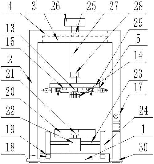
[0021] The present invention is specifically described below in conjunction with accompanying drawing, as Figure 1-5 As shown, a drilling machine includes a base (1), the base (1) is fixedly installed on the ground, a movable workbench mechanism is provided on the surface of the base (1), and a There is a door-shaped bracket (2), the bottom of the column of the door-shaped bracket (2) is fixedly installed on the ground on both sides of the base (1), and the upper surface of the beam of the door-shaped bracket (2) is provided with a The through groove (3) in the length direction, the upper surface of the beam on both sides of the through groove (3) is provided with a groove (4) with the same length as the through groove (3), and the groove (4) is installed with A horizontal sliding mechanism, the lower end of the horizontal sliding mechanism is fixedly equipped with a lifting and rotating mechanism, and the bottom of the lifting and rotating mechanism is fixedly installed with...


PUM


Abstract

The invention discloses a drilling machine. The machine comprises a base which is fixedly mounted on the ground, wherein a movable worktable mechanism is arranged on the surface of the base; a door shaped bracket is arranged on the base; the bottom end of an upright column of the door shaped bracket is fixedly mounted on the grounds at two sides of the base; a through groove is formed in the upper surface of a cross beam of the door shaped bracket along the length direction of the cross beam; concave grooves which are as long as the through hole are formed in the upper surfaces of the cross beam sections at two sides of the through hole; transverse sliding mechanisms are mounted in the concave grooves; lifting rotating mechanisms below which multi-arm tool switching drilling mechanisms are fixedly mounted are fixedly mounted at the lower ends of the transverse sliding mechanisms; a controller is arranged on one upright column surface of the door shaped bracket and can be correspondingly electrically connected to the movable worktable mechanism, the transverse sliding mechanisms, the lifting rotating mechanisms and the multi-arm tool switching drilling mechanisms. The drilling machine has the beneficial effects that the structure is simple, and the practicability is high.

Description

technical field [0001] The invention relates to metal working machines, in particular to a drilling machine. Background technique [0002] At present, the tool changing device of most drilling machines is located on the column of the drilling machine spindle, and needs to be moved to the tool magazine when changing the tool, which will prolong the processing time and increase the labor intensity. Contents of the invention [0003] The purpose of the present invention is in order to solve the above-mentioned problem, has designed a kind of drill press. [0004] The technical solution of the present invention to achieve the above object is, a drilling machine, including a base, the base is fixedly installed on the ground, a movable workbench mechanism is provided on the surface of the base, and a door-shaped bracket is provided above the base, The bottom ends of the columns of the door-shaped bracket are fixedly installed on the ground on both sides of the base, and the upp...

Claims


Application Information

Patent Timeline
Patent Type & Authority Patents(China)
IPC IPC(8): B23P23/02B23Q3/157
CPCB23P23/02B23Q3/15713
Inventor 尹建贺郑胜华蒋辉东
Owner XUANCHENG JIANLIN MACHINERY
Why Eureka
Try Eureka