
Pulse-free discharging screw rod device

A discharge screw and rod device technology, applied in the field of conveying machinery, can solve the problems of powder conveying discontinuity, non-quantification, pulsation, etc., and achieve the effect of avoiding pulse discharge and reducing the filling factor

Inactive Publication Date: 2016-02-24
天津中外建输送机械有限公司
View PDF0 Cites 0 Cited by
  • Summary
  • Abstract
  • Description
  • Claims
  • Application Information

AI Technical Summary

Problems solved by technology

When the production enterprises, especially those producing powder coatings, use the circular tube screw conveyor commonly used in the prior art to transport powders with high fluidity, this high fluidity and screw conveyor structure brings the difficulty of powder transportation. Discontinuity, pulsation and non-quantitative problems have caused a series of problems such as large negative pressure fluctuations and material spillage in downstream mixing equipment or processing equipment

Method used


Image

  • Pulse-free discharging screw rod device
  • Pulse-free discharging screw rod device
  • Pulse-free discharging screw rod device

Examples


Embodiment

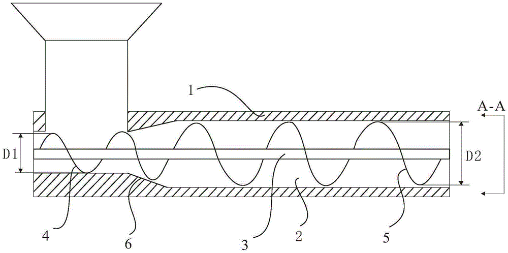
[0013] Such as figure 1 Shown is a non-pulse discharge screw device, including a hopper and a screw conveyor; the screw conveyor includes a tube wall 1 and a lumen 2; a screw 3 is installed in the lumen 2, and the screw Rotating leaves are installed on the rod 3.

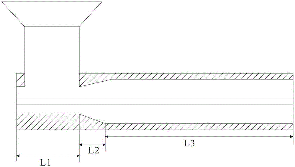
[0014] Such as figure 2 As shown, the pipe wall 1 is divided into feeding section L1, transition section L2 and feeding section L3 in turn according to the conveying direction; the feeding section L1 is located below the feeding hopper; the lumen of the feeding section L1 The inner diameter H1 is smaller than the inner diameter H2 of the lumen of the feeding section L3; the part of the tube wall 1 where the thickness of the tube wall gradually decreases between the feeding section L1 and the feeding section L3 is the transition section L2, so The inner diameter of the lumen 2 gradually increases in the transition section L2. The transition section L2 is preferably arranged as a slope 6 . This design of the pres...


PUM


Abstract

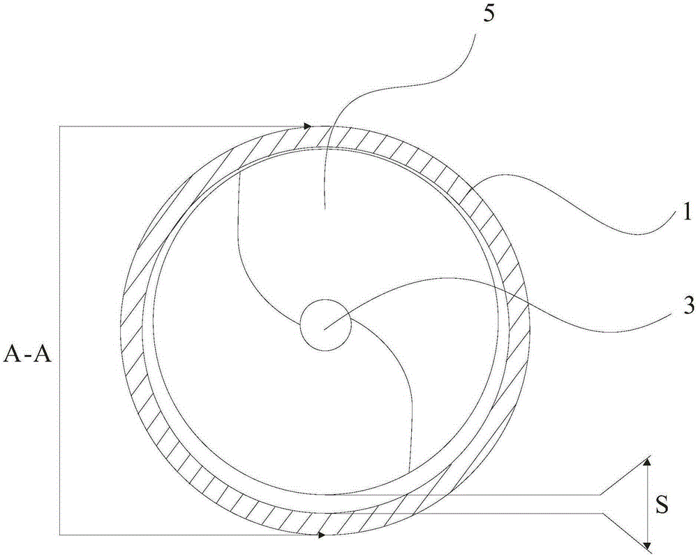
The invention discloses a pulse-free discharging screw rod device. Rotating blades are mounted on a screw rod; a tube wall is sequentially divided into a feeding section L1, a transition section L2 and a conveying section L3; a part, positioned at the feeding section L1, of a helical blade is a feeding helical blade; a part, positioned at the conveying section L3, of the helical blade is a conveying helical blade; the helical outer diameter ratio of the feeding helical blade to the conveying helical blade is 1:(1.3-1.5); a gap is formed between the lower end of the conveying helical blade and the inner bottom surface of the tube wall. By arranging the gap, a material, positioned at the bottom of a tube chamber, of a power coating does not rotate with the helical blade but is conveyed forwards by pushing of the helical blade, so that the powder coating is stably conveyed.

Description

technical field [0001] The invention relates to the technical field of conveying machinery, in particular to a non-pulse discharge screw device. Background technique [0002] Screw conveyors are commonly used continuous conveying machinery. When the production enterprises, especially those producing powder coatings, use the circular tube screw conveyor commonly used in the prior art to transport powders with high fluidity, this high fluidity and screw conveyor structure brings the difficulty of powder transportation. Discontinuity, pulsation and non-quantitative problems have caused a series of problems such as large negative pressure fluctuations in downstream mixing equipment or processing equipment, and material spillage. Contents of the invention [0003] The object of the present invention is to provide a non-pulse discharging screw device aiming at the technical defects existing in the prior art. [0004] The technical solution adopted to achieve the purpose of the...

Claims


Application Information

Patent Timeline
Patent Type & Authority Applications(China)
IPC IPC(8): B65G33/26B65G33/14
CPCB65G33/26B65G33/14B65G2812/0527B65G2812/0561B65G2812/0577
Inventor 张鹏张萌王凤忠
Owner 天津中外建输送机械有限公司
Learn More