
A water filter pit and its application

A soil collection pit and water filtration technology, which is applied to water supply devices, waterway systems, drainage structures, etc., can solve the problems of high moisture content in dregs, difficulty in transportation, and low transportation efficiency, so as to reduce water content and construction costs , Improve the effect of construction efficiency

Active Publication Date: 2017-04-26
CHINA CONSTR COMM ENG GRP UNITED
View PDF7 Cites 0 Cited by
  • Summary
  • Abstract
  • Description
  • Claims
  • Application Information

AI Technical Summary

Problems solved by technology

[0004] The first purpose of the present invention is to provide a filter water collection pit to solve the problem of difficult transportation, low transportation efficiency, easy abandonment and difficult disposal of dregs produced by shield tunneling due to their high moisture content or muddy state. question
[0005] The second purpose of the present invention is to provide an application of a filter water collection pit to solve the problem of difficulty in transportation, low transportation efficiency, easy abandonment and disposal of muck generated by shield tunneling due to its high moisture content or muddy state. technical issues

Method used


Image

  • A water filter pit and its application
  • A water filter pit and its application
  • A water filter pit and its application

Examples


Embodiment Construction

[0044] Hereinafter, embodiments of the filter sump and applications thereof of the present invention will be described with reference to the accompanying drawings.

[0045] The examples described here are specific specific implementations of the present invention, and are used to illustrate the concept of the present invention. They are all explanatory and exemplary, and should not be construed as limiting the implementation of the present invention and the scope of the present invention. In addition to the embodiments described here, those skilled in the art can also adopt other obvious technical solutions based on the claims of the application and the contents disclosed in the description, and these technical solutions include adopting any obvious changes made to the embodiments described here. Replacement and modified technical solutions.

[0046] The accompanying drawings in this specification are schematic diagrams, which assist in explaining the concept of the present in...


PUM


Abstract

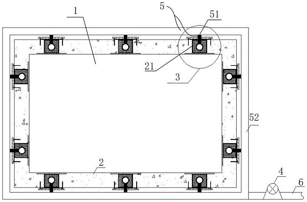
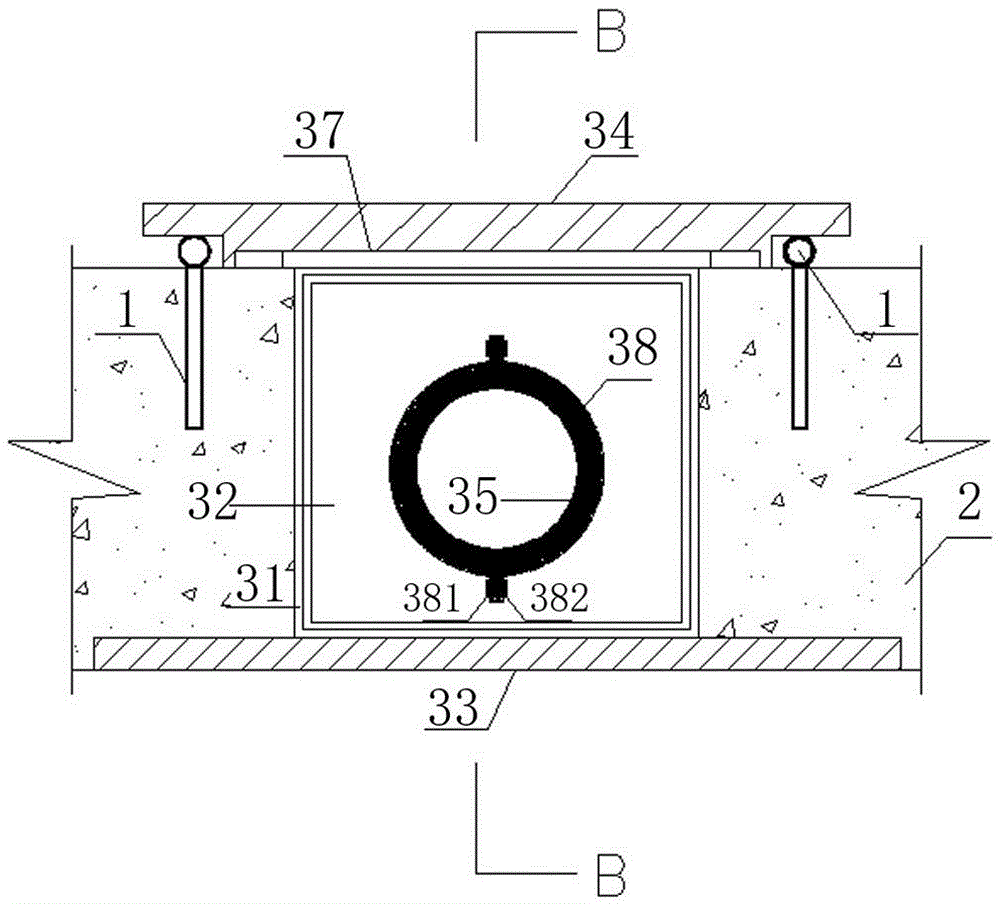
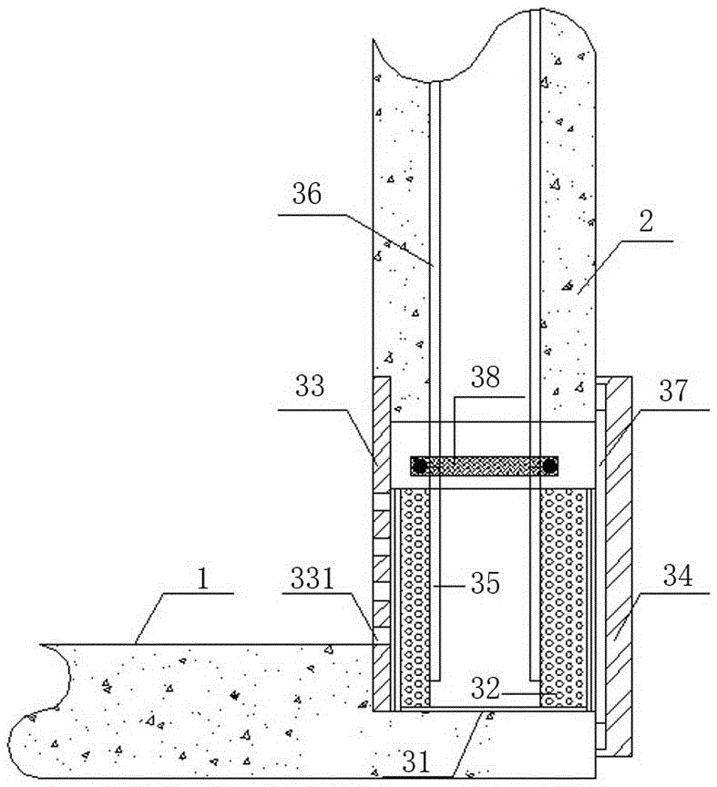
The invention discloses a water-draining residue soil collecting pit and application thereof. The water-draining residue soil collecting pit comprises a residue soil collecting pit bottom plate and a residue soil collecting pit side wall, and further comprises water collecting joints and water pumping equipment. The residue soil collecting pit side wall is provided with water collecting holes at intervals; each water collecting hole comprises an inner end and an outer end; and the water collecting holes are formed in the lower portion of the side wall. The water collecting joints are arranged in the water collecting holes of the water collecting pit side wall at intervals and used for collecting water in residue soil. The water pumping equipment is communicated with the water collecting joints through connecting pipes, and used for discharging water in the connecting pipes to a draining pipe which is connected with the water pumping equipment. By the water collecting joints arranged in the lateral wall of the residue soil-collecting pit, water in the residue soil collecting pit can be pumped in time by the water pumping equipment in time, water content of residue soil is lowered, transportability and disposal of residue soil are improved, transportation work amount is reduced, and transport cost is lowered. Water pumped from the residue soil collecting pit is treated into water for dust settling on construction sites, flushing toilets, synchronous grouting or slurry preparing and the like, so that the water resource is saved while the construction cost is lowered.

Description

technical field [0001] The invention belongs to the technical field of shield tunneling, and in particular relates to a filter water collection pit and its application. Background technique [0002] As the most advanced super-large special equipment for tunneling today, the shield machine is a high-tech construction equipment that realizes excavation, excavation, support, etc., and is widely used in urban rail transit, railways, highways, municipal administration, hydropower, etc. tunnel Engineering. [0003] During the construction of the earth pressure balance shield, as the shield machine excavates, the rock and soil cut by the cutter head are mixed with the improved materials and are continuously conveyed to the muck truck through the screw conveyor and belt, and then transported to the ground by the electric locomotive and the gantry crane In the soil collection pit, it will be transported by earth truck to the city's designated spoil ground. In the past, the moisture...

Claims


Application Information

Patent Timeline
Patent Type & Authority Patents(China)
IPC IPC(8): E03F5/10E03F5/14E03F3/02E03F3/04
CPCE03F3/02E03F3/04E03F5/10E03F5/101E03F5/14
Inventor 尹清锋王文学张洪涛郝本峰郭宏智朱英伟王太平王庆宏尉百有
Owner CHINA CONSTR COMM ENG GRP UNITED
Learn More