
Special tool for binding tail wires of stay wires of power transmission line tower

A technology for transmission lines and special tools, which is applied in the field of special tools for binding tail wires of transmission line poles and towers. It can solve the problems of complex device structure, high production cost, and easy loss, and achieve firm binding, low production cost, and reduced binding strength. Effect

Inactive Publication Date: 2016-02-24
SANMENXIA POWER SUPPLY COMPANY OF STATE GRID HENAN ELECTRIC POWER +1
View PDF6 Cites 11 Cited by
  • Summary
  • Abstract
  • Description
  • Claims
  • Application Information

AI Technical Summary

Problems solved by technology

Its disadvantage is that the structure of the device is complicated, the production cost is high, it is not anti-theft, and it is easy to lose

Method used


Image

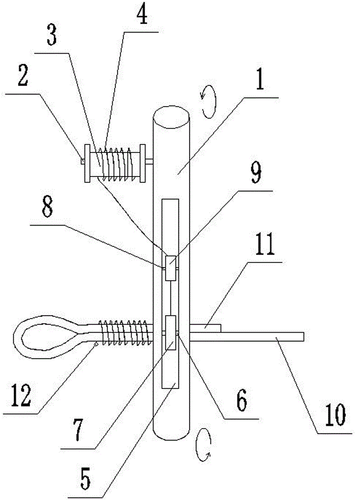
  • Special tool for binding tail wires of stay wires of power transmission line tower
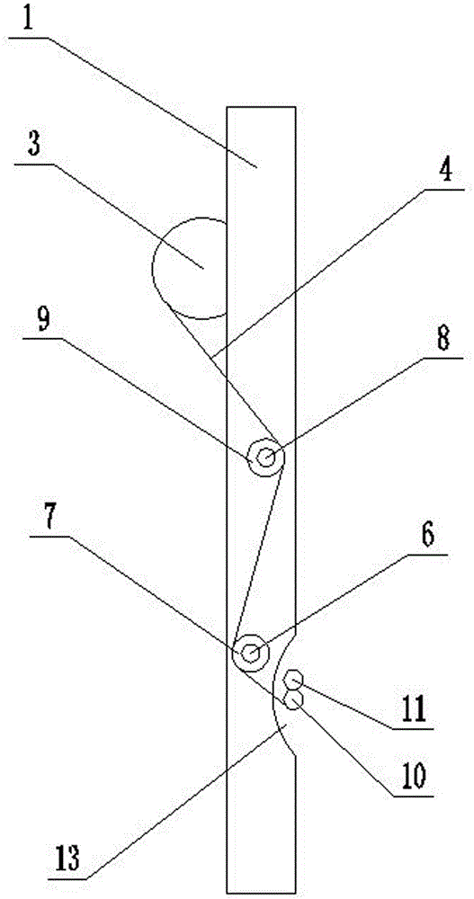
  • Special tool for binding tail wires of stay wires of power transmission line tower
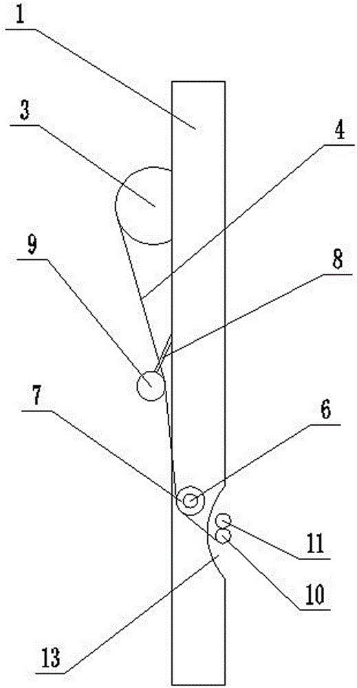
  • Special tool for binding tail wires of stay wires of power transmission line tower

Examples


Embodiment 1

[0019] Such as figure 1 As shown, this embodiment provides a special tool for binding tail wires of transmission line poles and towers, including a main body 1. The main body 1 can be a cylinder, a cuboid or a prism. figure 2 As shown, the side of the main body 1 is provided with a groove 13 for pressing the main wire 10 and the tail wire 11 against. The cross section of the groove 13 is arc-shaped. The side of the main body 1 is vertically and fixedly connected with a first connecting shaft 2, and the first connecting shaft 2 is rotatably connected with a wire roller 3, and the inside of the opening 5 is vertically and fixedly connected with a second connecting shaft 6. Two connecting shafts 6 are rotatably connected with iron wire winding wheels 7 .

[0020] The opening 5 of the main body 1 is vertically fixedly connected with a third connecting shaft 8, and the third connecting shaft 8 is rotatably connected with a crimping roller 9, and the crimping roller 9 is located b...

Embodiment 2

[0023] Such as image 3 As shown, the special tool for binding the tail wires of the transmission line poles and towers in this embodiment is basically the same as the structure of the first embodiment, the difference is that the third connecting shaft 8 is arranged on the upper surface of the main body 1, and the third connecting shaft The vertical distance between 8 and the first connecting shaft 2 in the horizontal direction is greater than the vertical distance between the second connecting shaft 6 and the first connecting shaft 2 in the horizontal direction.


PUM


Abstract

The invention provides a special tool for binding tail wires of stay wires of a power transmission line tower. The special tool comprises a main body, wherein the middle of the main body is provided with an opening, the lower bottom face of the main body is provided with grooves which main wires and the tail wires of the stay wires abut against in a pressing mode, a first connecting shaft is fixedly connected to the side face of the main body, an iron wire roller is connected to the first connecting shaft in a rotating mode, a second connecting shaft is fixedly connected into the opening, and an iron wire winding wheel is connected to the second connecting shaft in a rotating mode. The special tool is simple in structure, quite low in manufacture cost and capable of quickly binding the tail wires of the stay wires firmly, lowering binding strength and improving working efficiency.

Description

technical field [0001] The invention relates to the field of installation of power transmission line equipment, in particular to a special tool for binding tail wires of power transmission line poles and towers. Background technique [0002] Under normal circumstances, there are currently two commonly used methods for binding the tail wires of transmission line poles and towers. One is to fix them with steel wire clips (commonly known as little tigers), and the other is to use iron wires to wind and bind them. Fastening with steel wire clips is to use steel wire clips to combine the main wire and tail wire of the cable, and fasten them with steel wire clips. The production efficiency is not too low, but it is easy to be stolen. Iron wire binding is to use wire cutters to wind and tighten the steel wire circle by circle. It takes nearly 30 circles to meet the requirement of 10 centimeters required by the specification. Manual binding is time-consuming and laborious, and the ...

Claims


Application Information

Patent Timeline
Patent Type & Authority Applications(China)
IPC IPC(8): E04H12/20
CPCE04H12/20
Inventor 范腾黄进田华鑫付光路王国良张如意蒋红宣
Owner SANMENXIA POWER SUPPLY COMPANY OF STATE GRID HENAN ELECTRIC POWER
Learn More