Differential hydraulic cylinder control loop

A control circuit and hydraulic cylinder technology, applied in the direction of fluid pressure actuators, servo motors, servo motor components, etc., can solve the problems of slow hydraulic cylinder extension speed, non-reusable, low work efficiency, etc., to improve work efficiency , increase the extension speed, the effect is remarkable

Active Publication Date: 2016-02-24
HUBEI JIANGSHAN HEAVY IND
View PDF4 Cites 6 Cited by
  • Summary
  • Abstract
  • Description
  • Claims
  • Application Information

AI Technical Summary

Problems solved by technology

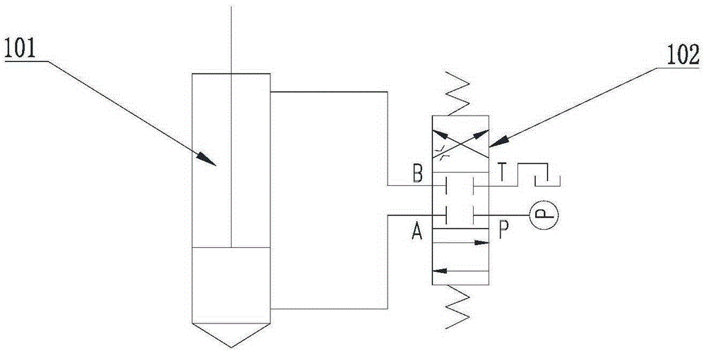
[0003] The first is the commonly used differential hydraulic cylinder control circuit, refer to the attached figure 1 , this circuit can realize the extension and retraction of the hydraulic cylinder, but has no other special functions. There is no special function in this circuit, and the differential control of the hydraulic cylinder and the regeneration of hydraulic energy in the rodless cavity cannot be realized.
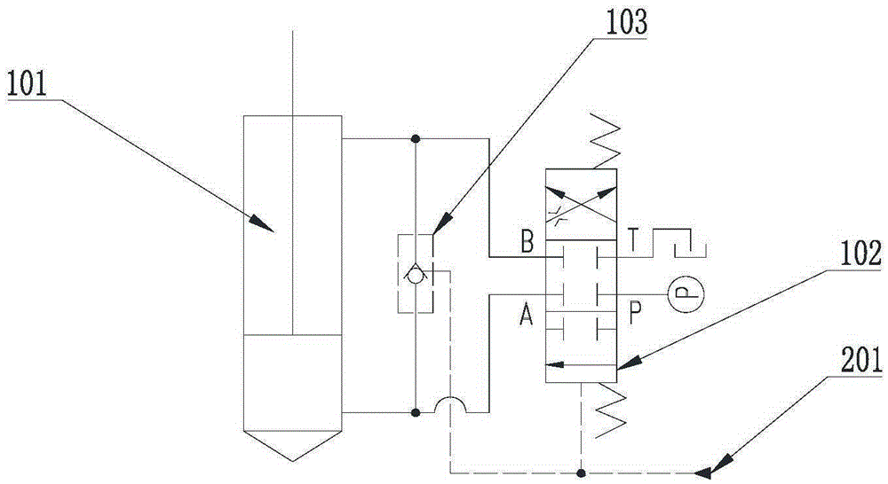
[0004] The second is the common hydraulic cylinder differential control circuit, refer to the attached figure 2 , when the differential hydraulic cylinder works in the first working quadrant, that is, under the condition of pressure extension, the hydraulic oil in the rod chamber in the circuit is connected with the rodless chamber through the external control check valve to realize differential control. Increase the extension speed of the hydraulic cylinder to improve its working efficiency. Although this circuit realizes the differential control of the hydraulic cylinder alone, it cannot realize the system flow regeneration, and cannot regenerate the high-pressure hydraulic energy in the rodless cavity when the hydraulic cylinder is retracted. use
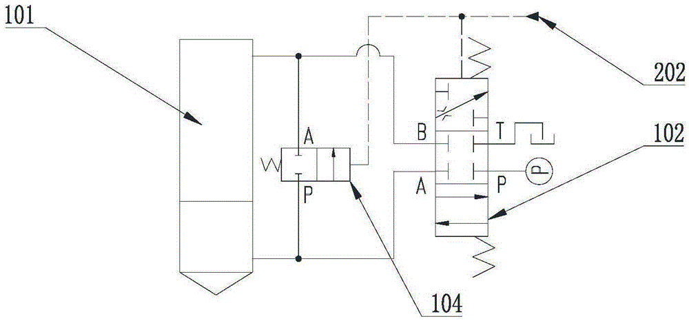
[0005] The third control loop is the differential hydraulic cylinder flow regeneration control loop, refer to the attached image 3 , when the differential hydraulic cylinder works in the second working quadrant, that is, under the compressed working condition, the hydraulic oil in the rodless cavity in the circuit is connected with the rod cavity through the flow regeneration valve, so that part of the rodless cavity returns oil Into the rod cavity, so as to achieve flow regeneration, to achieve the purpose of energy saving and emission reduction, but can not realize the differential control of the hydraulic cylinder, the extension speed of the hydraulic cylinder is slow, and the work efficiency is low
Working in the first and second working quadrants at the same time is the most common working environment for differential hydraulic cylinders, but there is no application circuit that satisfies the two functions of rapid propulsion and energy reuse

Method used


Image

  • Differential hydraulic cylinder control loop
  • Differential hydraulic cylinder control loop
  • Differential hydraulic cylinder control loop

Examples


Embodiment Construction

[0017] In order to make the purpose, content, and advantages of the present invention clearer, the specific implementation manners of the present invention will be further described in detail below in conjunction with the accompanying drawings and embodiments.

[0018] like Figure 4 As shown, the present invention provides a differential hydraulic cylinder control circuit, including a differential hydraulic cylinder 101, a directional control valve 301, a first check valve 105, a second check valve 106, a variable throttle valve 107, and a flow regeneration valve 108, the differential connection control valve 109; the two oil outlets A and B of the directional control valve 301 communicate with the rodless cavity and the rod cavity of the differential hydraulic cylinder 101 respectively to form a main circuit; the differential connection control valve 109. The second one-way valve 106 constitutes a differential connection control branch; the variable throttle valve 107, the f...


PUM


Abstract

The invention relates to a differential hydraulic cylinder control loop. The differential hydraulic cylinder control loop mainly consists of a differential hydraulic cylinder, a direction control valve, a one-way valve, a variable throttle valve, a flow regeneration valve and a differential connecting control valve, wherein the differential connecting control valve and the one-way valve are formed to a differential connecting control branch; and the variable throttle valve, the flow regeneration valve and the one-way valve are formed to a flow regeneration control branch. The differential hydraulic cylinder control loop integrates the hydraulic cylinder differential control loop with the flow regeneration loop, and is more comprehensive in functions; when the hydraulic cylinder performs a pressed extension motion, the loop achieves an effect of the differential control loop, so that the extension speed of the hydraulic cylinder can be accelerated, and the working efficiency is improved; and when the hydraulic cylinder performs a pressed shrinkage motion, the loop achieves an effect of the flow regeneration loop, so that high hydraulic pressure in a rodless cavity of the differential cylinder can be reused to achieve the purposes of energy conservation and emission reduction.

Description

technical field [0001] The invention belongs to the field of hydraulic cylinder control, and in particular relates to a differential hydraulic cylinder control circuit. Background technique [0002] As a basic hydraulic control circuit, the differential hydraulic cylinder control circuit has been widely used in industrial hydraulics, construction machinery, etc., increasing the hydraulic cylinder extension speed, and at the same time realizing the energy reuse in the rodless cavity when the hydraulic cylinder is retracted. topic of application. There are mainly three types of existing differential hydraulic cylinder control circuits, and their working principles, advantages and disadvantages are as follows: [0003] The first is the commonly used differential hydraulic cylinder control circuit, refer to the attached figure 1 , this circuit can realize the extension and retraction of the hydraulic cylinder, but has no other special functions. There is no special function in...

Claims


Application Information

Patent Timeline
Patent Type & Authority Applications(China)
IPC IPC(8): F15B11/08F15B13/04
CPCF15B11/08F15B13/04
Inventor 杨阳靳敏郭良涛方安国杨立成梁珺张震许经伟
Owner HUBEI JIANGSHAN HEAVY IND
Why Eureka
Try Eureka