
Pneumatic valve using air cylinder as actuator

A technology of actuators and cylinders, applied to engine components, valve details, valve devices, etc., can solve problems such as valve jamming, potential safety hazards, and elastic decline of return springs, so as to solve the problem of insufficient spring force, eliminate potential safety hazards, and increase the effect force effect

Inactive Publication Date: 2016-02-24
ANHUI LIUGUO CHEM CO LTD
View PDF4 Cites 3 Cited by
  • Summary
  • Abstract
  • Description
  • Claims
  • Application Information

AI Technical Summary

Problems solved by technology

However, in the actual production process, due to reasons such as the valve control medium and the service life of the valve, for example, the return spring in the cylinder of the actuator has a decline in elasticity after long-term use, or the valve stem or valve core is rusted, or it is blocked by debris. Many factors, such as valve jamming, often occur, the valve cannot normally complete the condition or fully open and fully close operation, which brings safety hazards to production.

Method used


Image

  • Pneumatic valve using air cylinder as actuator

Examples


Embodiment Construction

[0016] The technical solutions in the embodiments of the present invention will be clearly and completely described below in conjunction with the accompanying drawings.

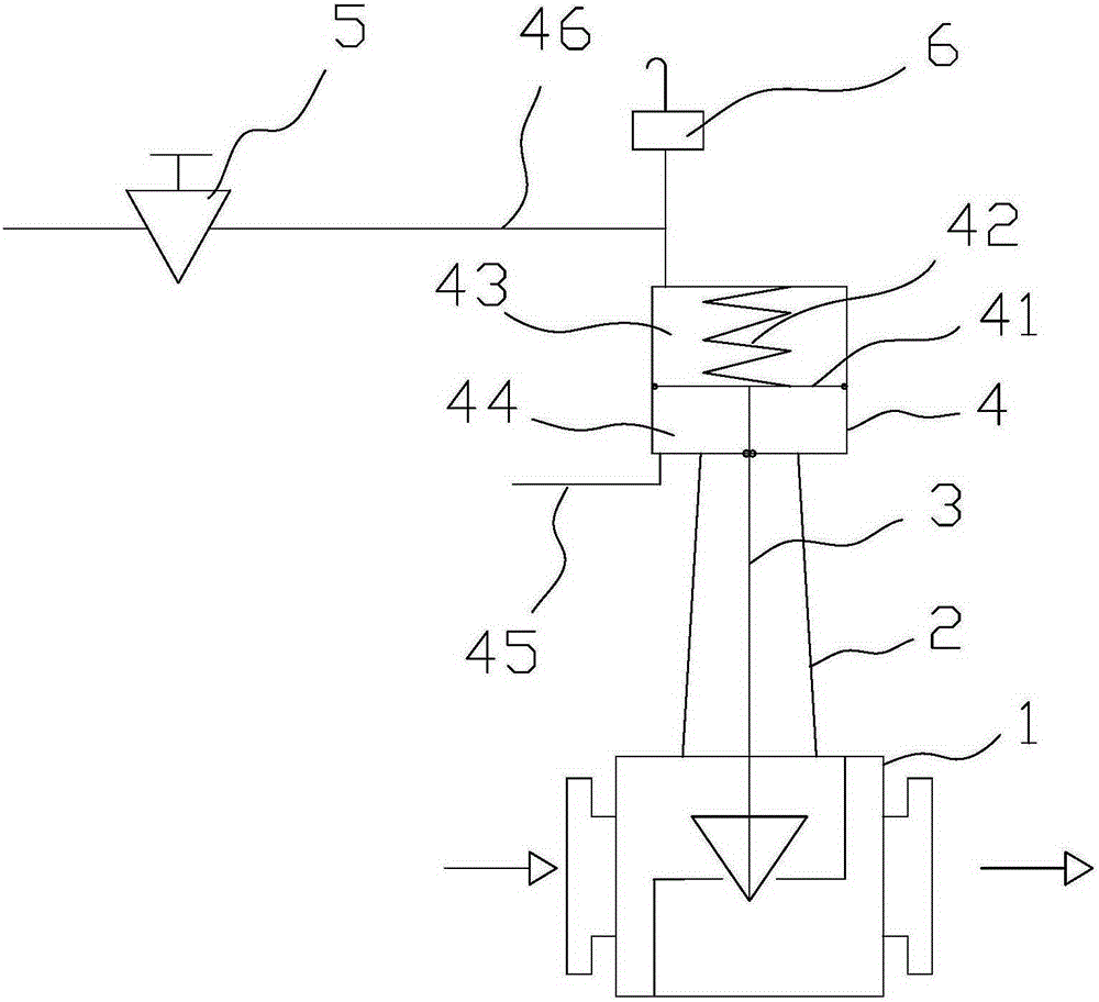
[0017] Such as figure 1 As shown, the present invention includes a valve body 1, a valve rod 3, and a cylinder 4 that controls the reciprocating action of the valve rod 3. The cylinder 4 is fixed to the valve body 1 by a bracket 2, and one end of the valve rod 3 is connected with the piston rod of the cylinder 4. The piston 41 in the cylinder 4 divides the inner cavity of the cylinder into two working chambers, one of the working chambers 43 is provided with a return spring 42, the other working chamber 44 is in communication with the control air circuit through the air pipe 45, and the cylinder 4 is equipped with a return spring The exhaust port of the working chamber 43 of 42 has an air inlet pipe 46 in communication with the control air path through the pressure reducing filter 5, and a pressure release valve...


PUM


Abstract

The invention discloses a pneumatic valve using an air cylinder as an actuator. The pneumatic valve comprises a valve body, a valve rod, and the air cylinder for controlling the valve rod to reciprocate, wherein the air cylinder is fixed to the valve body through a bracket; one end of the valve rod is connected to a piston rod of the air cylinder; a returning spring is arranged in one working chamber of the air cylinder, and another working chamber of the air cylinder communicates with a control air channel through an air tube; an air feeding tube at the air exhausting port of the working chamber, provided with the returning spring, of the air cylinder, communicates with the control air channel; a pressure releasing valve is mounted on the air feeding tube. According to the pneumatic valve, a stable pressure air source is charged to the returning spring side of the air cylinder, thus the acting force of the returning spring to a piston of the air cylinder can be increased, and as a result, the problem of blocking of the valve due to insufficient spring force can be solved, the valve can be smoothly operated, and the potential risk can be removed.

Description

Technical field [0001] The invention relates to a pneumatic control valve, in particular to a pneumatic control valve with a cylinder as an executive element. Background technique [0002] Generally, the valve with the cylinder as the actuator is a single-acting valve, that is, the control air source communicates with a working chamber of the cylinder. When the compressed air enters the working chamber, the piston rod of the cylinder expands or contracts to drive the valve rod connected to it. Advance or retreat to control the opening or closing of the valve. In chemical production, when the instrument air fails to supply air or the electrical fails to supply power, the valve needs to be in the fault position (fully open or fully closed) to ensure the safety of chemical production. However, in the actual production process, due to the valve control medium and valve service life and other reasons, such as the elasticity of the return spring in the actuator cylinder after long-ter...

Claims


Application Information

Patent Timeline
Patent Type & Authority Applications(China)
IPC IPC(8): F16K31/122
CPCF16K31/1221
Inventor 刘威吴辉丁隆贵
Owner ANHUI LIUGUO CHEM CO LTD
Learn More