Blunt impact indicator methods

An indicator, blunt technology, used in the field of systems for monitoring and indicating high-energy impacts on structures, which can solve the problem of visible indication of damage

Active Publication Date: 2016-02-24
THE BOEING CO
View PDF11 Cites 4 Cited by
  • Summary
  • Abstract
  • Description
  • Claims
  • Application Information

AI Technical Summary

Problems solved by technology

[0004] Although a technique to make visible to the casual observer a high-energy blunt impact on an aircraft by placing an impact strip (comprising rupturable microspheres filled with a colored indicator fluid) on the surface of an aircraft structure susceptible to such an impact Methods of indication are well known, however, in some cases a visual indication of surface damage may not be desired
[0005] There is room for improvement in existing techniques for monitoring or indicating high energy blunt impacts on structures such as aircraft

Method used


Image

  • Blunt impact indicator methods
  • Blunt impact indicator methods
  • Blunt impact indicator methods

Examples


Embodiment Construction

[0101] For purposes of illustration only, various embodiments of blunt impact indicators employing fluid-filled microspheres will now be described in detail. These blunt impact indicators may be applied to the surface of the structure in the form of a substrate (eg, a tape or applique) with an adhesive backing. Microspheres can be attached to a substrate or embedded in a coating applied to the substrate.

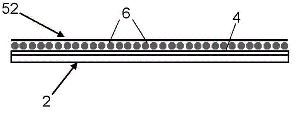
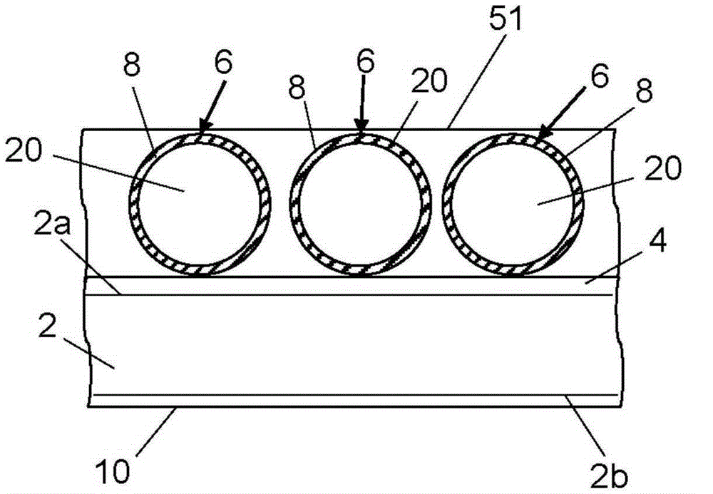
[0102] figure 1 A first illustrative embodiment of a blunt impact indicator of the aforementioned type is schematically depicted. The blunt impact indicator comprises a substrate 2 having a plurality of hollow microspheres 6 attached to one surface of the substrate 2 by a layer 4 of adhesive material (hereinafter "adhesive layer 4") and distributed thereon . Optionally, the microspheres 6 are covered by a cover layer 52 .

[0103] The substrate 2 can have different forms. In some cases, substrate 2 may be in the form of a strip comprising thin strips of plastic material...


PUM


Abstract

The application discloses a blunt impact indicator method. Systems and methods using fluid-filled hollow microspheres to assist in monitoring or indicating high-energy blunt impacts on structures such as aircraft. A multiplicity of microspheres may be adhered to or embedded in a coating applied on a surface of a substrate (e.g., a tape or an applique), which substrate in turn can be adhered to a surface of a structure to be monitored. The microspheres are designed to rupture at one or more specified pressure thresholds. In some embodiments, the microspheres are filled with electrically conductive fluid which, if released from ruptured microsphere, changes the electromagnetic state of the substrate. In response to the detection of a sufficiently large change in the electromagnetic state of the substrate, a blunt impact indication is generated. The impact site may then undergo nondestructive inspection.

Description

technical field [0001] The present disclosure generally relates to systems and methods for monitoring and indicating high energy impacts to structures. More specifically, the present disclosure relates to systems and methods for measuring the magnitude and location of high energy impact events. Background technique [0002] When damage to structural components is suspected, non-destructive evaluation (NDE) techniques are often used to monitor the structural integrity of potentially damaged components. Quickly identifying specific damage points can be difficult when using NDE techniques because large areas of the structure may need to be scanned. Therefore, it is desirable to have a technology that can easily determine the precise damage location. [0003] In the aviation industry, aircraft can be subjected to high energy loads from logistics vehicles and ground support equipment such as belt loaders, luggage carts, aircraft refuelers, catering vehicles, ground power units,...

Claims


Application Information

Patent Timeline
Patent Type & Authority Applications(China)
IPC IPC(8): G01N27/90G01N25/72G01N27/02
CPCB64D45/00G01L1/247G01M5/0091G01M9/00G01P15/06G01M5/0083G01L5/0052H01H29/002H01H35/146G01N27/90B64F5/60G01N3/00G01L5/14
Inventor G·E·乔治森W·J·塔皮亚
Owner THE BOEING CO
Why Eureka
Try Eureka