

Anti-surge circuit
A anti-surge and circuit technology, applied in the field of circuits, can solve problems such as unsatisfactory effects and unsatisfactory circuits
- Summary
- Abstract
- Description
- Claims
- Application Information
AI Technical Summary
Problems solved by technology
Method used
Image

Examples
Embodiment Construction
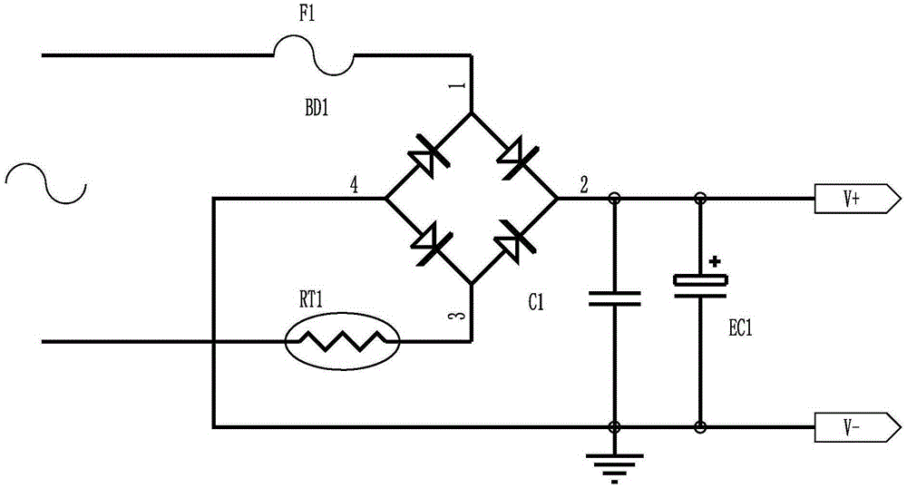
[0012] figure 1 For the existing NTC surge current suppression circuit, its defects have been described above, and will not be repeated here.
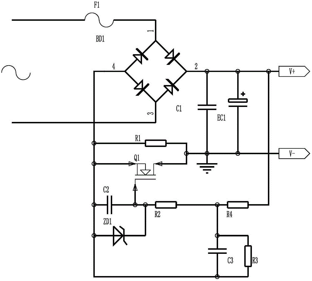
[0013] refer to figure 2 , an anti-surge circuit of the present invention, including high-power resistor R1, MOS tube Q1, resistor R2, resistor R3, resistor R4, voltage regulator tube ZD1, capacitor C1, electrolytic capacitor EC1, capacitor C3, capacitor C2, bridge stack BD1 and fuse F1, one end of the capacitor C1 is connected to the positive pole of the electrolytic capacitor EC1, one end of the resistor R4 and the positive pole of the bridge stack BD1, the other end of the capacitor C1, the negative pole of the electrolytic capacitor EC1, the drain of the MOS transistor Q1 and the resistor One end of R1 is grounded, the other end of resistor R1 is connected to the negative pole of bridge stack BD1, the source of MOS transistor Q1, one end of capacitor C2, the anode of voltage regulator tube ZD1, one end of capacitor C3 and one end...
PUM
 Abstract
Description
Claims
Application Information