Conduction time generation circuit for power supply converter, and power supply converter

A power converter and a technology for generating circuits, which are applied in the direction of adjusting electrical variables, converting DC power input to DC power output, instruments, etc., can solve the problems of slow duty cycle adjustment speed and slow dynamic response speed, and achieve fast recovery of output voltage. Constant, impact-reducing effect

Active Publication Date: 2016-02-24
SILERGY SEMICON TECH (HANGZHOU) CO LTD
View PDF12 Cites 21 Cited by
  • Summary
  • Abstract
  • Description
  • Claims
  • Application Information

AI Technical Summary

Problems solved by technology

[0005] In view of this, the purpose of the present invention is to provide a turn-on time generation circuit and power converter for power converters, which are used to solve...

Method used


Image

  • Conduction time generation circuit for power supply converter, and power supply converter
  • Conduction time generation circuit for power supply converter, and power supply converter

Examples


Embodiment Construction

[0016] Preferred embodiments of the present invention will be described in detail below with reference to the accompanying drawings, but the present invention is not limited to these embodiments. The present invention covers any alternatives, modifications, equivalent methods and schemes made within the spirit and scope of the present invention.

[0017] In order to provide the public with a thorough understanding of the present invention, specific details are set forth in the following preferred embodiments of the present invention, but those skilled in the art can fully understand the present invention without the description of these details.

[0018] In the following paragraphs the invention is described more specifically by way of example with reference to the accompanying drawings. It should be noted that all the drawings are in simplified form and use inaccurate scales, which are only used to facilitate and clearly assist the purpose of illustrating the embodiments of t...


PUM


Abstract

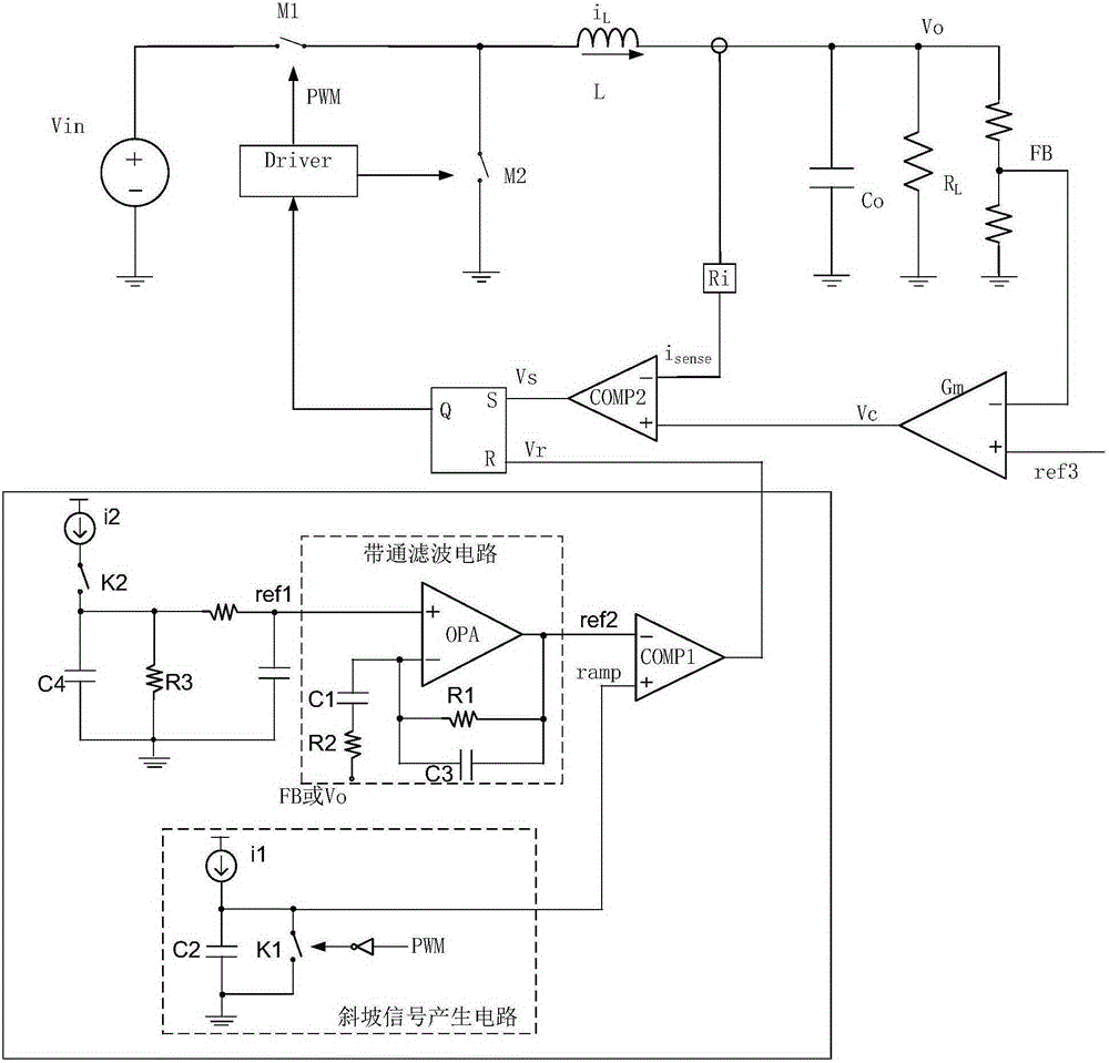
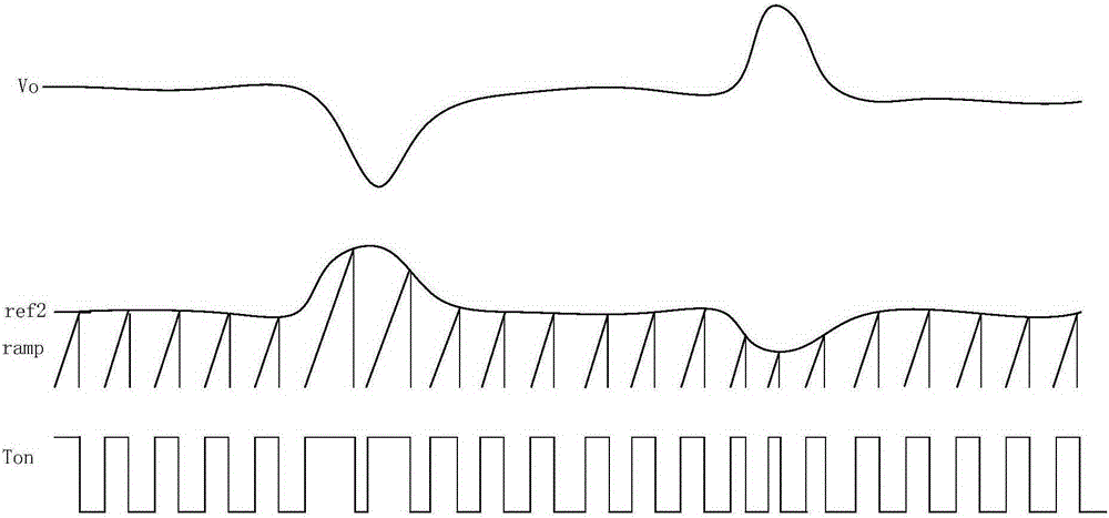
The invention discloses a conduction time generation circuit for a power supply converter, and a power supply converter. According to the invention, a band-pass filtering circuit is additionally arranged, DC components of second reference signals are equal to first reference signals, a differentiating circuit has a differential effect, can rapidly react to change of output voltages, timely performs feedback and adjustment, and the change trench of AC components of the second reference signals is opposite to the change trench of the output voltages. According to the invention, in case of abrupt change of the output voltages, the second reference signals can timely perform feedback and adjustment so as to reduce influences generated due to the abrupt change of the output voltages and enable the output voltages to be rapidly recovered to be constant.

Description

technical field [0001] The invention relates to the technical field of power electronics, in particular to a turn-on time generating circuit for a power converter and the power converter. Background technique [0002] The power converter realizes the expected output through the voltage conversion of the power stage circuit, and keeps the output voltage constant, that is, adjusts the output voltage by controlling the conduction state of the main power switch tube in the power stage circuit. Therefore, it is necessary to sample the output voltage and implement feedback to control the on-off state of the main power switch tube according to the comparison result of the output voltage and the corresponding reference voltage. [0003] In the fixed on-time working mode, the output voltage sampling signal is error-processed with the corresponding reference voltage to obtain a feedback compensation signal, and the feedback compensation signal is compared with the current sampling sig...

Claims


Application Information

Patent Timeline
IPC IPC(8): H02M3/155H02M1/08
CPCH02M1/08H02M3/155
Inventor 罗迪
Owner SILERGY SEMICON TECH (HANGZHOU) CO LTD
Why Eureka
Try Eureka