
Vehicle main transmission and control method thereof

A main drive, vehicle technology, applied in the direction of transmission, control device, vehicle components, etc., can solve the problems of easy misoperation, no differential function, inconvenient operation, etc., and achieve good driving performance and overall structure. Compact, easy-to-operate mechanism

Active Publication Date: 2018-09-11
JIANGSU XCMG CONSTR MASCH RES INST LTD
View PDF18 Cites 7 Cited by
  • Summary
  • Abstract
  • Description
  • Claims
  • Application Information

AI Technical Summary

Problems solved by technology

[0007] (1) When the rotation direction of the active bevel gear remains unchanged, only the reverse rotation of the unilateral output shaft can be realized, that is, the vehicle can only realize in-situ steering in one direction, and the in-situ steering in the opposite direction needs to be realized by changing the rotation direction of the active bevel gear , the manipulation method is inconvenient, prone to misoperation, and the transmission does not have a differential function when turning in situ
[0008] (2) Does not have a differential function, only suitable for the transmission system of the crawler chassis, not suitable for high-speed road vehicles

Method used


Image

  • Vehicle main transmission and control method thereof
  • Vehicle main transmission and control method thereof
  • Vehicle main transmission and control method thereof

Examples


Embodiment 1

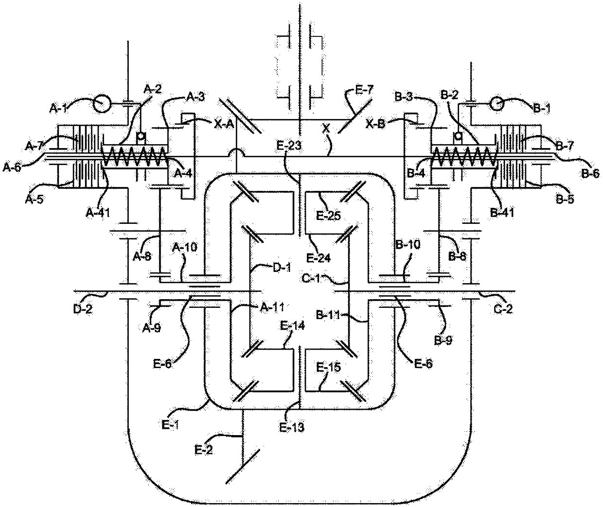
[0051] In this embodiment, the driven bevel gear 102 is fixedly connected to the housing 105 of the first differential, and the gear shaft of the driven bevel gear is coaxially arranged with the left half shaft and the right half shaft of the first differential; Two planetary gears 104 / 108 are arranged on the planetary shaft 103 of a differential, and the first differential drives the side gears located on both sides of the planetary shaft to rotate through the two planetary gears. The number of planetary gears can also be arranged into 4 according to transmission requirements, which is prior art.

[0052] In the first differential and the second differential, the side gears 109 / 106 / 210 / 209 / 309 / 310 are in driving connection with the corresponding side shaft ends through involute splines.

[0053] The right half shaft of the second differential in the left commutator assembly 2 is the same shaft 110 as the left half shaft of the first differential; The right half shaft of a di...

Embodiment 2

[0069] refer to Figure 4 In the illustrated embodiment, in this embodiment, the main reducer assembly 1 is a conventional final reducer structure, the driven bevel gear 102 is fixedly connected with the first differential case 105; the planetary gears 104 and 108 are arranged on the planetary On the shaft 103, meshed with the side gears 106 and 109, the planetary gears of the first differential can be arranged in two according to transmission requirements (such as Figure 4 middle 104 and 108) or four; both ends of the left half shaft 110 and the right half shaft 107 are arranged with involute splines, and the opposite ends of the two are matched with the involute splines on the side gears 109 and 106 respectively .

[0070] The rotation of the driven bevel gear 102 prompts the planetary shaft 103 fixedly connected to the first differential housing 105 to drive the planetary gears 104 and 108 to rotate, and when there is no differential speed, the left half shaft 110 and the...


PUM


Abstract

The invention discloses a vehicle main transmission and a control method thereof. The vehicle main transmission comprises a shell, a main speed reducer assembly and a bilateral commutator assembly, wherein the main speed reducer assembly and the bilateral commutator assembly are located in the shell; the bilateral commutator assembly comprises a second differential, a check ring and a locking ring, the locking ring comprises a second engaging tooth capable of achieving linkage or separation of an output axle shaft and a second differential shell, and the check ring comprises a fourth engagingtooth capable of limiting rotation of the second differential shell. through the locking ring and the check ring, the second differential shell is controlled to rotate, linkage between the second differential shell and the output axle shaft is controlled, the autonomous differential function of output shafts on the two sides under the condition that a vehicle normally runs is achieved, and it is ensured that the vehicle has the good driving performance; when the output shafts on the two sides have the reverse needs, under the condition that a driving conical gear does not change the rotating direction, positive and negative rotation of the output shafts on the two sides can be conveniently and rapidly achieved, meanwhile, the differential function is kept, and the transmission is compact in whole structure, convenient to control and wide in application range.

Description

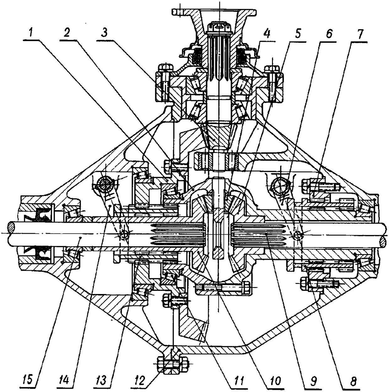
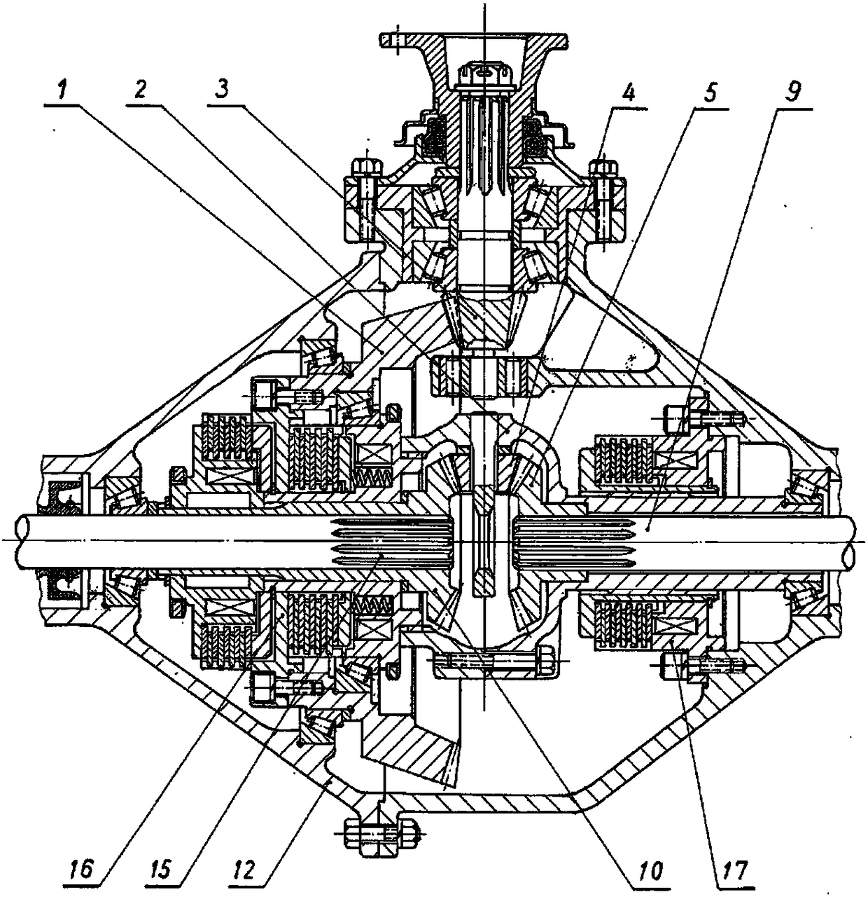
technical field [0001] The invention relates to the technical field of mechanical transmission devices of vehicles, in particular to a vehicle main transmission capable of realizing vehicle steering on the spot and a control method thereof. Background technique [0002] In the field of vehicle design, reducing the turning radius of the vehicle as much as possible is an important aspect of improving vehicle performance. After several generations of efforts, some special mechanisms and manipulation methods have been developed so that the vehicle can achieve in-situ The steering function has greatly improved the driving performance of the vehicle, but some structures are too complicated to be popularized, and some structures still have a lot of room for performance improvement. [0003] figure 1 Shown is the vehicle main drive disclosed by the patent CN101559714A, where the left and right half shafts can rotate in opposite directions, and provides a vehicle main drive in which...

Claims


Application Information

Patent Timeline
Patent Type & Authority Applications(China)
IPC IPC(8): F16H57/023F16H48/20F16H48/08
CPCF16H48/08F16H48/20F16H57/023Y02T10/62
Inventor 李勇董鲁波张勇
Owner JIANGSU XCMG CONSTR MASCH RES INST LTD
Learn More