Automobile part cleaning system with capability of monitoring cleaning state
A technology for auto parts and cleaning systems, applied in the field of auto parts cleaning systems, can solve the problems of poor cleaning quality, difficult to effectively remove residual sand and oil pollution of auto parts, waste of water resources, etc., and achieve good cleaning quality and removal of residual sand. and oil pollution, the effect of saving water
- Summary
- Abstract
- Description
- Claims
- Application Information
AI Technical Summary
Problems solved by technology
Method used
Image
Examples
Embodiment 1
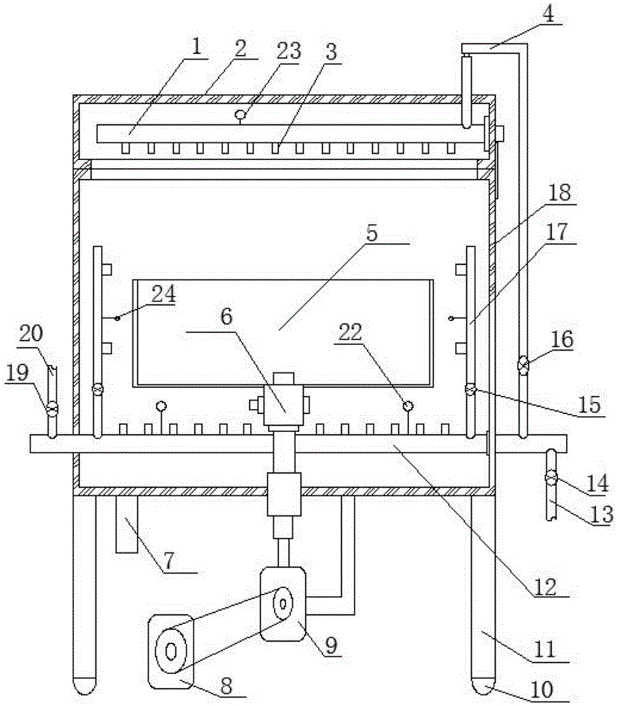
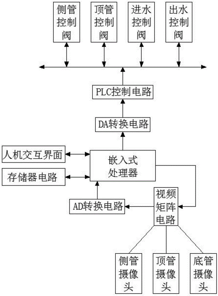
[0025] A kind of auto parts cleaning system capable of monitoring the cleaning state, such as figure 1 , figure 2 As shown, the following structure is specially set up: including a cleaning device and an intelligent control system connected with the cleaning device, and the intelligent control system is provided with an embedded processor, a video matrix circuit, an AD conversion circuit DA conversion circuit, and a PLC control system. Circuit, camera group, described embedded processor is connected with AD conversion circuit, video matrix circuit, DA conversion circuit respectively, and described video matrix circuit is connected with AD conversion circuit, and described video matrix circuit is connected with camera group, Described DA conversion circuit is connected with PLC control circuit, and described PLC control circuit is connected with cleaning device; Described cleaning device comprises casing 18, case cover 2, and described case cover 2 is hinged on the upper openi...
Embodiment 2
[0028] This embodiment is further optimized on the basis of any of the above embodiments, further to better realize the present invention, such as figure 1 , figure 2 As shown, the following structure is particularly arranged: the top spray main pipe 1 is also provided on the top spray main pipe 1, and a plurality of spray branch pipes 3 are also arranged on the top spray main pipe 1, and the tank cover 2 is closed In the case of the box body 18, the water outlet of the spray branch pipe 3 on the top spray main pipe 1 is downward; the camera group is also provided with a pipe top camera 23, and the pipe top camera 23 is arranged on the top spray main pipe 1 , the top spray main pipe 1 is connected to the bottom spray main pipe 12 through a water diversion pipe 4, and a pipe jacking control valve 16 is arranged on the water diversion pipe 4, and the pipe jacking control valve 16 is connected to a PLC control circuit.
[0029]The water flow of the top spray main pipe 1 is cont...
Embodiment 3
[0031] This embodiment is further optimized on the basis of any of the above embodiments, further to better realize the present invention, such as figure 1 , figure 2 As shown, the following structure is specially arranged: the water diversion pipe 4 is placed outside the box body 18, and the water diversion pipe 4 is connected with the top spray main pipe 1 through the hose 21, and it is convenient to place the water diversion pipe 4 outside the box body 18 It is also convenient for inspection and maintenance while being controlled. At the same time, in order to avoid interference when the tank cover 2 and the tank body 18 are opened or closed, the hose 21 is specially used to connect with the top nozzle main pipe 1, thereby effectively avoiding interference.
PUM
 Abstract
Description
Claims
Application Information
 - R&D
- Intellectual Property
- Life Sciences
- Materials
- Tech Scout
- Unparalleled Data Quality
- Higher Quality Content
- 60% Fewer Hallucinations
Browse by: Latest US Patents, China's latest patents, Technical Efficacy Thesaurus, Application Domain, Technology Topic, Popular Technical Reports.
© 2025 PatSnap. All rights reserved.Legal|Privacy policy|Modern Slavery Act Transparency Statement|Sitemap|About US| Contact US: help@patsnap.com


