Automatic welding equipment for impeller of multi-blade fan

An automatic welding and fan impeller technology, which is applied in the field of machinery, can solve problems such as uneven product quality, aggravated blade inclination angle, and difficulty in meeting design requirements with manual correction, and achieve good welding quality and high production efficiency.

Active Publication Date: 2016-03-02
ZHEJIANG XINGYI VENTILATOR ELECTRICAL APPLIANCE
View PDF8 Cites 4 Cited by
  • Summary
  • Abstract
  • Description
  • Claims
  • Application Information

AI Technical Summary

Problems solved by technology

Although the spot welding of the blade on the wheel disk is simple and efficient, the blade will tilt to both sides and cannot be perpendicular to the wheel disk. In addition, when the subsequent wheel cover is welded, in order to ensure the tight fit between the wheel cover and the blade, an axial force, but it will increase the inclination angle of the blade
Therefore, manual correction is still difficult to meet the design requirements
The other is manual spot welding. The level of welding technology also has a great influence on the welding quality of the impeller. The product quality is uneven, which seriously affects the product quality.

Method used


Image

  • Automatic welding equipment for impeller of multi-blade fan
  • Automatic welding equipment for impeller of multi-blade fan
  • Automatic welding equipment for impeller of multi-blade fan

Examples


Embodiment Construction

[0016] The following are specific embodiments of the present invention and in conjunction with the accompanying drawings, the technical solutions of the present invention are further described, but the present invention is not limited to these embodiments.

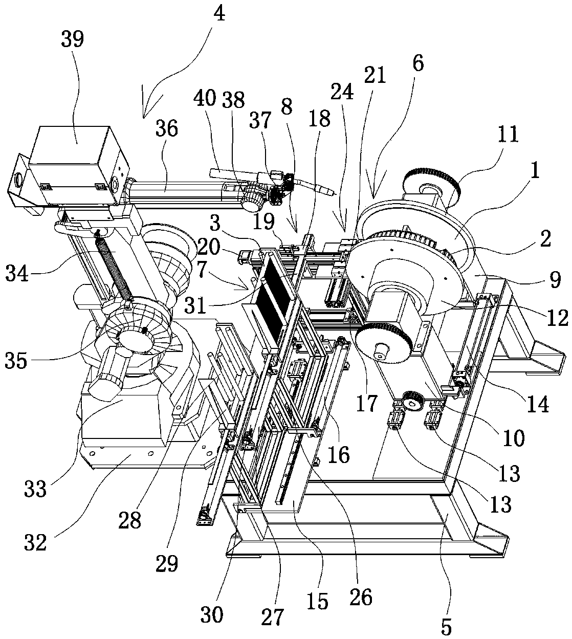
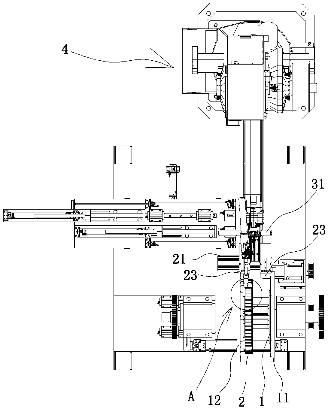
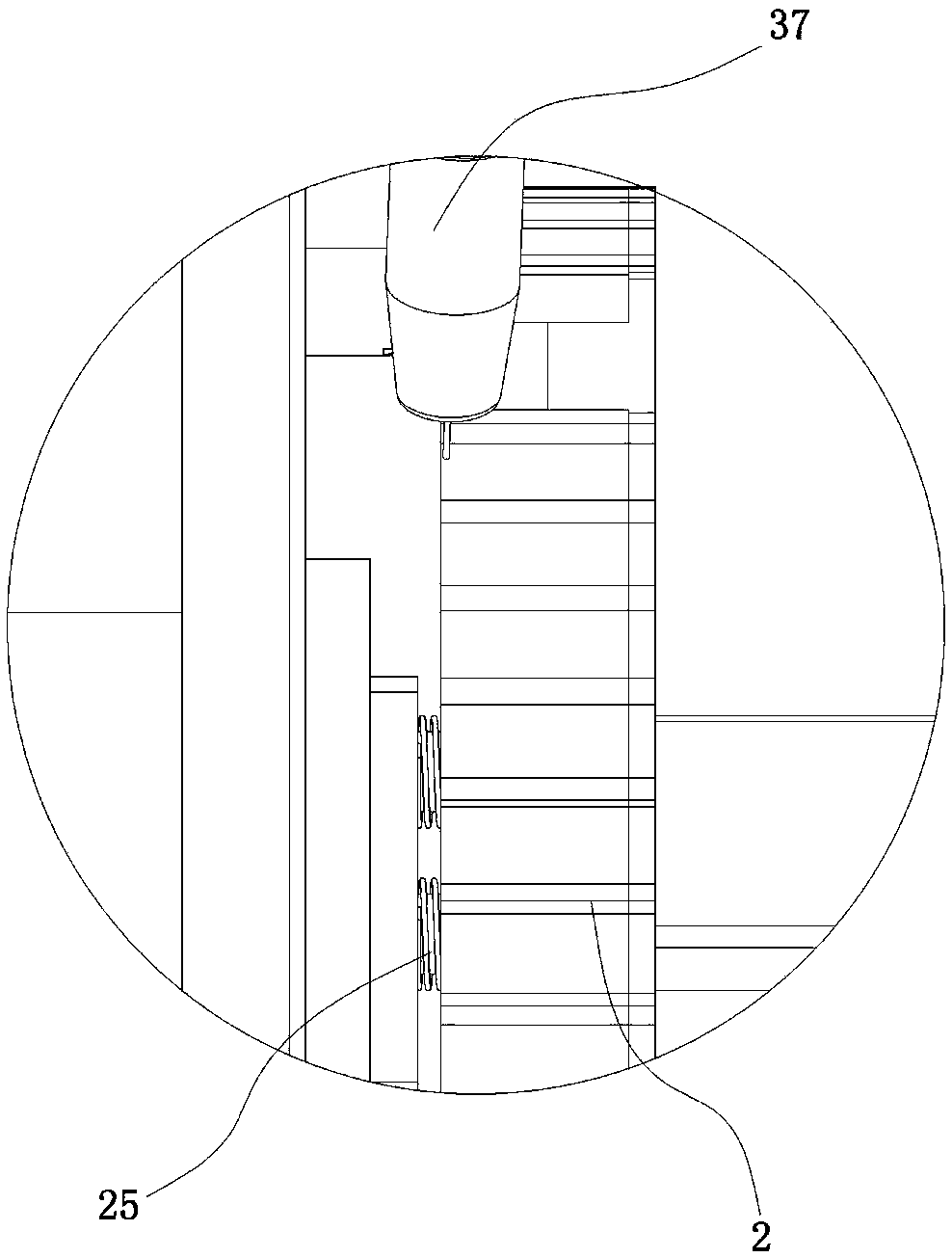
[0017] Such as figure 1 , figure 2 , image 3 As shown, the automatic welding equipment for the multi-wing fan impeller is composed of a wheel disc 1, a wheel cover 2 and a blade 3. The equipment includes a welding robot 4, a frame 5 and a welding robot arranged on the frame 5. The tooling fixture 6, the stocker 7 and the pinch device 8, the tooling fixture 6 includes a column one 9 and a column two 10 fixedly connected to the frame 5, and a chuck one 11 is arranged between the column one 9 and the column two 10 With chuck two 12, the frame 5 is provided with a slide rail 13 for the column two 10 to move left and right, and the frame 5 is also provided with a cylinder one 14 that can promote the column two 10 to move on...


PUM


Abstract

The invention provides automatic welding equipment for an impeller of a multi-blade fan and belongs to the technical field of machines, aiming at solving the problems of the prior art that impellers of the existing multi-blades fan are low in production efficiency and poor in welding quality. The equipment comprises a welding robot, a rack and a work clamp, a storage device and a clamping and delivery device, wherein the work clamp comprises a stand column I and a stand column II which are fixedly connected to the rack; a chuck I and a chuck II are arranged between the stand column I and the stand column II; the rack is provided with a slide rail for the stand column II to move left and right and is also provided with a cylinder I capable of pushing the stand column II to move on the slide rail; the storage device is fixedly connected with the rack by a bottom plate; the bottom plate is provided with a slide rail for the storage device to move left and right and is also provided with a cylinder II capable of pushing the storage device to move on the slide rail; the clamping and delivery device comprises a support fixedly connected to the rack; the support is provided with a clamping jaw, a clamping cylinder and a cylinder III; and the opening and closing of the clamping jaw are controlled by the clamping cylinder. The automatic welding equipment has the advantages of being high in production efficiency, good in welding quality and the like.

Description

technical field [0001] The invention belongs to the technical field of machinery and relates to welding equipment, in particular to an automatic welding equipment for multi-blade fan impellers. Background technique [0002] In addition to the motor and volute, the important part of the fan is the impeller. The welding quality of the impeller parts not only affects the air volume, efficiency and life of the fan, but also affects the stability of the fan's motion balance, vibration and noise. Therefore, the quality of the impeller plays a very important role in the product. Due to the advantages of many blades, stable movement, small vibration, low noise, large flow rate and long life, the multi-wing fan is favored by the market and praised by consumers. [0003] The existing multi-blade fan impeller welding process is to manually spot-weld the blades on the wheel disc, and perform integral welding after spot-welding the wheel cover. Although the spot welding of the blade on...

Claims


Application Information

Patent Timeline
Patent Type & Authority Applications(China)
IPC IPC(8): B23K37/00B23K37/02B23K37/04B23K37/047
CPCB23K37/00B23K37/0252B23K37/0435B23K37/047
Inventor 余盛江
Owner ZHEJIANG XINGYI VENTILATOR ELECTRICAL APPLIANCE
Why Eureka
Try Eureka