
Multi-rotor UAV

A multi-rotor unmanned aerial vehicle and rotor protection technology, which is applied in the directions of rotorcraft, unmanned aerial vehicle, fuselage, etc., can solve the problems of unmanned aerial vehicle stability, poor firmness, poor flight load capacity, and insufficient lightness. Achieve the effect of improving stability and firmness, good flight load capacity, and high space utilization

Active Publication Date: 2017-11-14
HUNAN AIRTOPS INTELLIGENT TECH CO LTD
View PDF6 Cites 0 Cited by
  • Summary
  • Abstract
  • Description
  • Claims
  • Application Information

AI Technical Summary

Problems solved by technology

[0003] (1) The structure design of some UAVs is complex, the space utilization rate is not high, and the body is bulky but not light enough, resulting in poor flight load capacity and affecting the operation requirements of UAVs
[0004] (2) The overall stability and firmness of some drones are poor, and the components of the drone cannot support each other structurally, and good flight performance cannot be obtained during take-off, landing and flight
[0005] (3) The self-protection and safety of some UAVs are not enough. In case of a fall, the rotating rotor is easy to scratch the contact objects, and it is also easy to cause damage to the rotor
[0006] (4) Some UAVs are used as tethered aircraft and are connected to ground equipment through cables. However, due to unreasonable design, the pulled cables are likely to affect the flight stability of UAVs. There is also the problem of low precision

Method used


Image

  • Multi-rotor UAV
  • Multi-rotor UAV
  • Multi-rotor UAV

Examples


Embodiment Construction

[0036] The present invention will be described in further detail below in conjunction with specific embodiments and accompanying drawings.

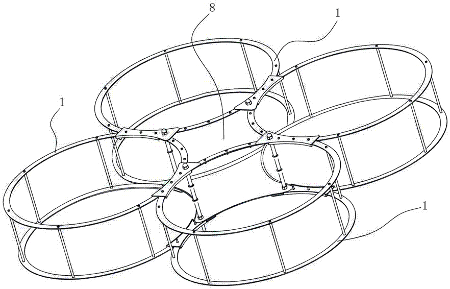
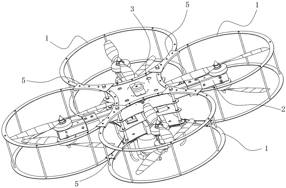
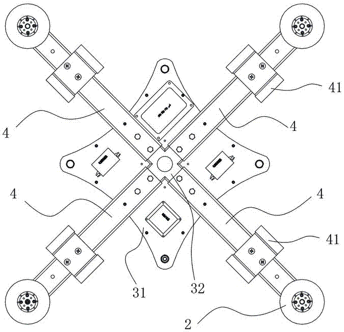
[0037] Such as Figure 1 to Figure 6 As shown, the present invention provides a multi-rotor UAV, comprising more than three rotor guards 1, each rotor guard 1 is provided with a propeller power assembly 2, and more than three rotor guards 1 are sequentially Connect each other to form a whole and form a closed cavity 8 at the center of the whole. A fuselage body 3 is arranged in the closed cavity 8. The fuselage body 3 includes more than two fuselage partitions 31 arranged horizontally. An installation space is formed between the bulkheads 31 . In this embodiment, the multi-rotor UAV is provided with four cylindrical rotor protection covers 1, and the four cylindrical rotor protection covers 1 are connected to each other in turn to form a whole, and a rhombus-shaped enclosing space is formed at the center of the whole. Cavity 8. Four fu...


PUM


Abstract

The invention discloses a multi-rotor unmanned aerial vehicle, comprising more than three rotor protection covers, each rotor protection cover is equipped with a propeller power assembly, and the three or more rotor protection covers are connected to each other in turn to form a whole An enclosing cavity is formed at the center of the whole, and a fuselage body is arranged in the enclosing cavity. The fuselage body includes more than two fuselage partitions arranged horizontally, and an installation space is formed between more than two fuselage partitions. The invention has the advantages of simple and compact structure, good body stability, good firmness, high safety and excellent flight efficiency.

Description

technical field [0001] The present invention mainly relates to the field of unmanned aerial vehicles, in particular to a multi-rotor unmanned aerial vehicle. Background technique [0002] In today's society, with the rapid rise of unmanned aerial vehicles, unmanned aerial vehicles are widely used in military, police and civilian fields. Wait. However, some existing drones have the following technical problems: [0003] (1) The structural design of some UAVs is complex, the space utilization rate is not high, and the body is bulky but not light enough, resulting in poor flight load capacity and affecting the operation requirements of UAVs. [0004] (2) The overall stability and firmness of some drones are poor, and the various components of the drone cannot support each other structurally, and good flight performance cannot be obtained during take-off, landing and flight. [0005] (3) The self-protection and safety of some UAVs are not enough. In case of a fall, the rotati...

Claims


Application Information

Patent Timeline
Patent Type & Authority Patents(China)
IPC IPC(8): B64C27/20B64C1/00B64C1/06B64F1/12B64C25/32
CPCB64C1/00B64C1/069B64C25/32B64C27/20B64F1/12B64C2025/325B64C2001/0045B64U10/10
Inventor 罗世彬刘松吴雷
Owner HUNAN AIRTOPS INTELLIGENT TECH CO LTD
Learn More