Simple type conveyor for rough steel plates

A transmission device and a simple technology, which is applied in the field of steel ring processing, can solve the problems of shortening the service life of motors, high labor costs, and the weight of rough steel plates, etc., to achieve the effects of prolonging service life, high work efficiency, and saving manpower

Inactive Publication Date: 2016-03-02
CHONGQING CHUANGLONG IND
View PDF8 Cites 0 Cited by
  • Summary
  • Abstract
  • Description
  • Claims
  • Application Information

AI Technical Summary

Problems solved by technology

Among them, the required length of the steel plate is obtained by cutting the rough steel plate, but now generally needs to be manually transported to the lower end of the cutting machine, the rough steel plate itself is relatively heavy, and the labor cost is relatively high
[0004] For this reason, a number of evenly arranged rollers are now set up, driven by a motor, and the friction between the rollers and the steel plate is used to drive the steel plate to move forward, and the weight of the entire rough steel plate is pressed on the roller, and the motor needs a large enough force. , to drive the blank steel plate to move forward, which consumes more motor and shortens the service life of the motor

Method used


Image

  • Simple type conveyor for rough steel plates
  • Simple type conveyor for rough steel plates

Examples


Embodiment Construction

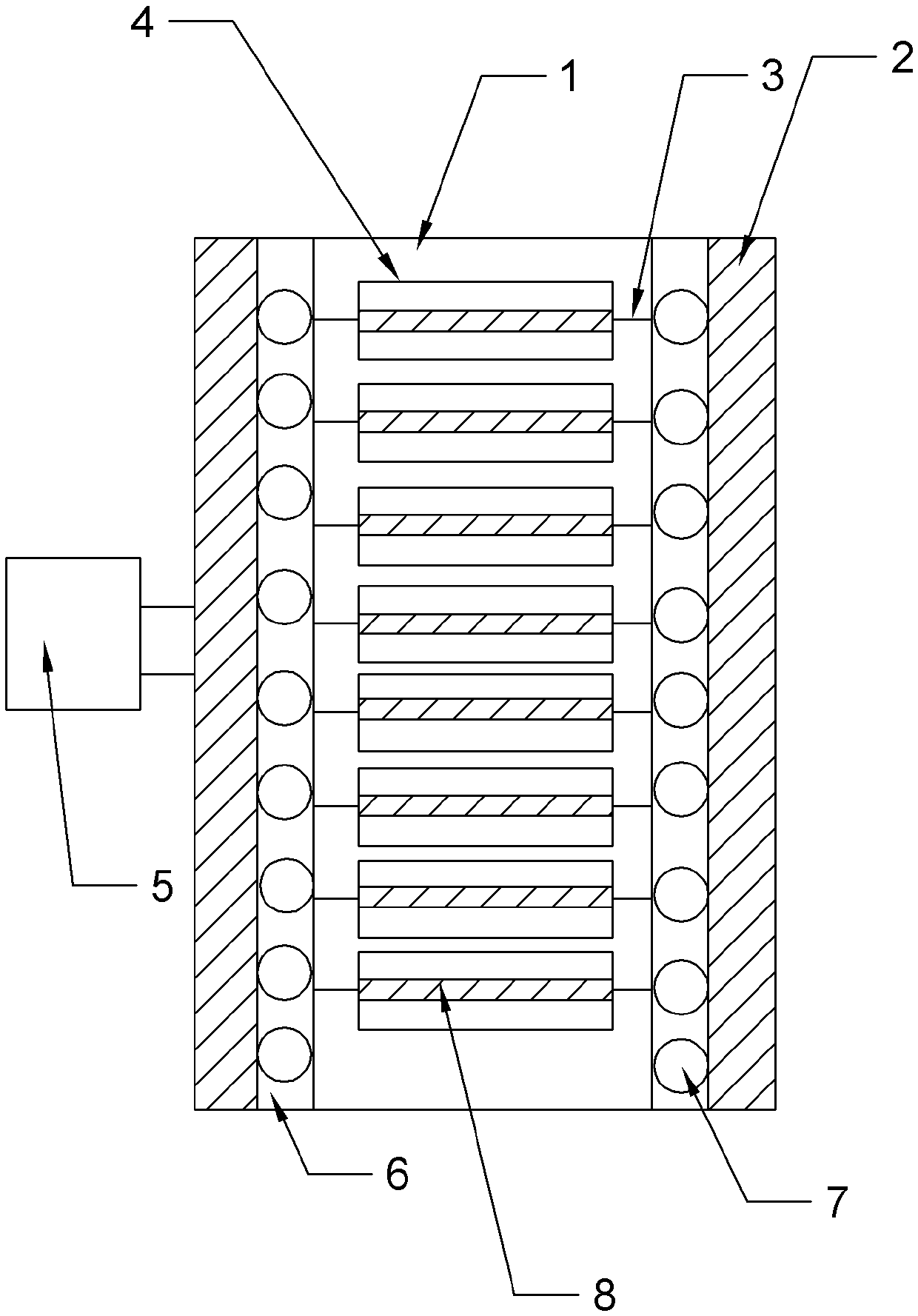
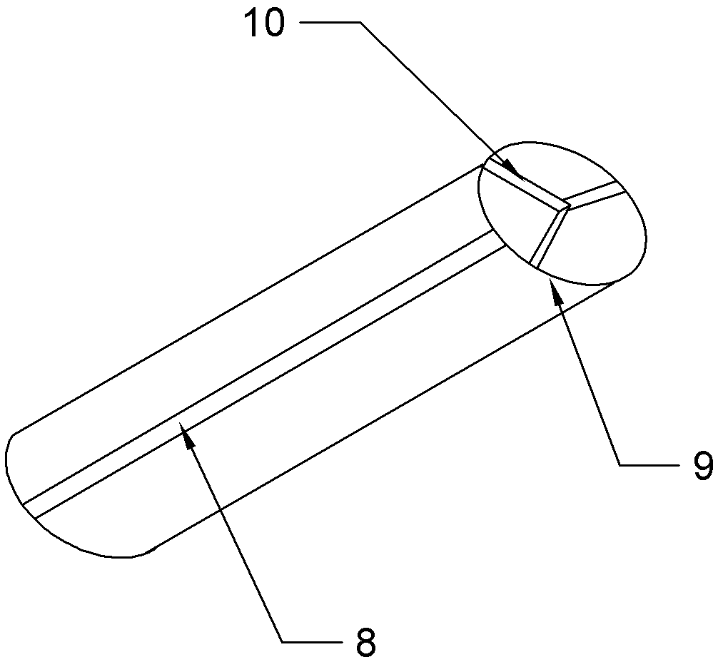
[0016] The marks in the accompanying drawings of the present invention are: working platform 1, baffle plate 2, rotating shaft 3, cylinder 4, motor 5, groove 6, roller 7, support rod 8, circular ring 9, pole 10.

[0017] Such as figure 1 and figure 2 As shown, the simple conveying device for rough steel plates includes a frame 1 and a working platform 1. The working platform 1 is fixed on the top of the frame 1, and a fixed plate is arranged under the frame 1. The fixed plate and the horizontal ground are connected by bolts. fixed. And working platform 1 is parallel with horizontal plane, and working platform 1 is laid with iron sheet, is convenient to working platform 1 is protected. Vertical baffles 2 are arranged on both sides above the working platform 1 respectively, and the baffles 2 are hinged with the working platform 1 to facilitate cleaning of debris on the working platform 1 . The baffles 2 are connected by the rotating shaft 3, the rotating shaft 3 is covered w...


PUM


Abstract

The invention relates to the field of steel ring processing, in particular to a simple type conveyor for rough steel plates. The simple type conveyor comprises a rack and a working platform, wherein the working platform is fixedly arranged on the upper surface of the rack; the two sides of the upper surface of the working platform are respectively provided with vertical baffle plates; the baffle plates are connected by virtue of rotary shafts; rollers are arranged on the upper surface of the rotary shafts in a sleeving mode; the adjacent rollers are arranged at intervals; a motor is arranged below the rack; the motor is connected with the rotary shafts; grooves are respectively formed in the upper surface, close to the two side walls of the baffle plates, of the working platform; rollers are mounted in the grooves; height of the rollers is the same as that of the rollers; each roller is formed by arranging at least three supporting rods in a peripheral direction; the side walls at the two ends of each roller are provided with supporting rods and circular rings; the supporting rods, in radial directions of a central point of each rotary shaft, are connected with the corresponding circular ring; and the cross section of the side wall of each roller is a star-shaped structure. According to the simple type conveyor, stress on the upper surface of the roller is resolved, so that load of the motor is relieved, and the service life of the motor is prolonged.

Description

technical field [0001] The invention relates to the field of steel ring processing, in particular to a simple conveying device for blank steel plates. Background technique [0002] Many motor vehicles such as trucks and vans generally use tubeless tires, commonly known as tubeless tires. Tubeless tires are similar to ordinary tires in appearance, the difference is that a layer of rubber sealing layer with a thickness of about 2 to 3mm is added to the inner wall of the tire, which is adhered by vulcanization. Yes, under the tread facing the sealing layer, there is a self-adhesive layer made of a special mixture of unvulcanized rubber. When the tire is punctured, the self-adhesive layer can bond the punctured hole by itself, so it is also called a tubeless tire with a self-adhesive layer. When the tubeless tire is punctured, the pressure will not drop sharply, which is conducive to safe driving. There is no friction and jamming between the inner and outer tires in the tubele...

Claims


Application Information

Patent Timeline
Patent Type & Authority Applications(China)
IPC IPC(8): B65G13/06B65G13/00B65G47/22
CPCB65G13/06B65G13/00B65G47/22B65G2201/022B65G2201/0223
Inventor 陈振丰
Owner CHONGQING CHUANGLONG IND
Why Eureka
Try Eureka