Waste gas turbocharger

A technology of exhaust gas turbine and supercharger, which is applied in the direction of gas turbine device, machine/engine, engine function, etc. It can solve the problems of no protection for exhaust gas turbocharger and increased weight of exhaust gas turbocharger, and achieve simple enclosure Effect of protection or burst protection, simple enclosure protection, simple burst protection

Inactive Publication Date: 2016-03-02
MAN ENERGY SOLUTIONS SA
View PDF8 Cites 2 Cited by
  • Summary
  • Abstract
  • Description
  • Claims
  • Application Information

AI Technical Summary

Problems solved by technology

However, on the one hand, due to the increased weight of this exhaust turbocharger and, on the other hand, these measures can only be employed with a newly designed exhaust turbocharger
In contrast, already exi

Method used


Image

  • Waste gas turbocharger
  • Waste gas turbocharger
  • Waste gas turbocharger

Examples


Embodiment Construction

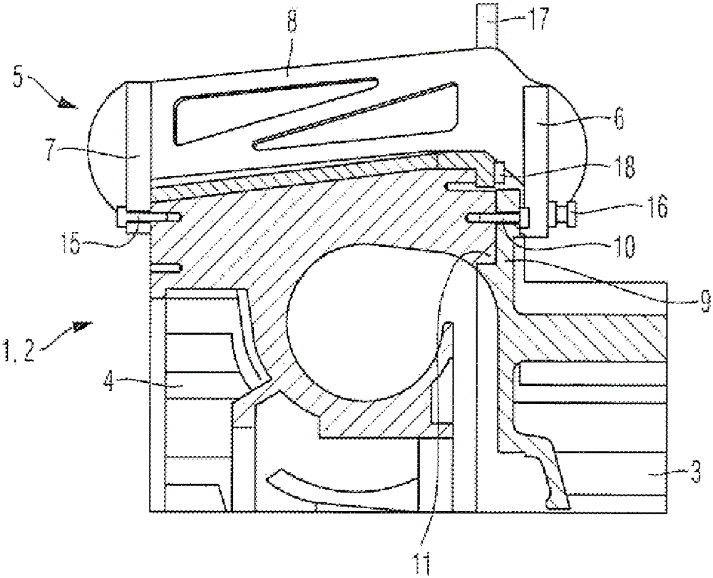
[0033] An exhaust turbocharger consists of a turbine and a compressor. The turbine of the exhaust gas turbocharger includes a multi-part turbine housing and a turbine rotor received in the turbine housing. The compressor of the exhaust gas turbocharger includes a compressor housing and a compressor rotor received in the compressor housing. The turbine rotor and compressor rotor are coupled to each other. The energy generated during the expansion of the exhaust gas in the region of the turbine is utilized in the compressor to compress the charge air.

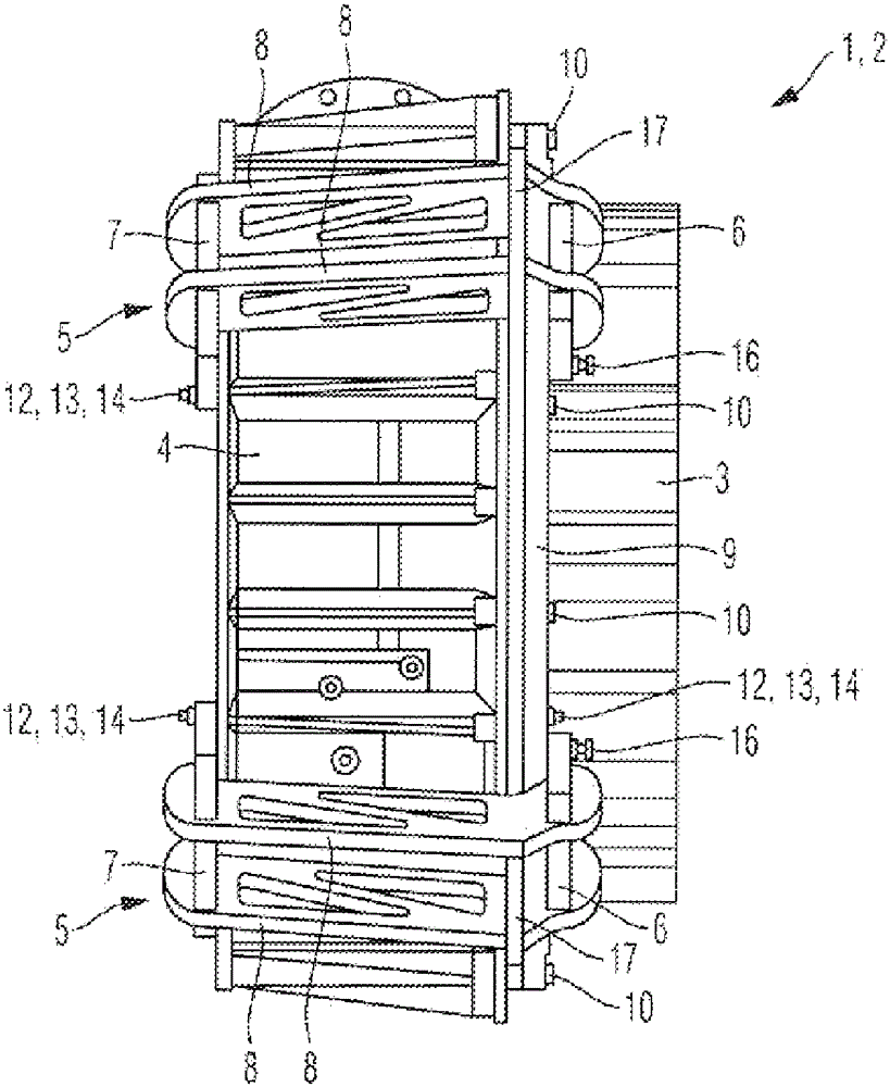
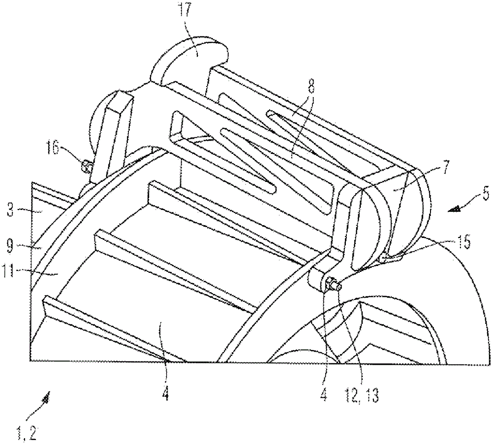
[0034] figure 1 An excerpt of the exhaust gas turbocharger shown in the area of ​​the compressor 1, ie the compressor housing 2, in which, in figure 1 The compressor housing 2 shown in is assembled from a bearing housing 3 and a volute 4 . figure 2 show through figure 1 A cross-sectional view of the compressor housing 2. image 3 shows a perspective view from the bearing housing 3, while Figure 4 A perspective view from ...


PUM


Abstract

A waste gas turbocharger is provided with a turbine for expanding exhaust gas and for recovering energy, and having a compressor (1) for compressing charge air with the aid of the energy obtained in the turbine, said turbine a multi-part, A joint of a screw turbine housing and in the comprises turbine housing positioned turbine rotor, said compressor (1) has a multi-part, a joint of a screw compressor housing (2) and one positioned in the compressor housing and coupled to the turbine rotor compressor rotor, and said housing parts of the multi-piece compressor housing (2) and / or housing parts of the multi-part turbine casing by means of at least one each of a clamp holder (5) are clamped.

Description

technical field [0001] The invention relates to exhaust gas turbochargers. Background technique [0002] An exhaust turbocharger consists of a turbine and a compressor. The turbine of the exhaust gas turbocharger is used to expand the exhaust gases leaving the engine and to generate energy during the expansion of the exhaust gases. The compressor of the exhaust gas turbocharger is used to compress the charge air to be supplied to the engine by means of the energy generated in the turbine. The turbine includes a multi-part turbine housing and a turbine rotor positioned within the turbine housing. The compressor includes a multi-part compressor housing and a compressor rotor positioned within the compressor housing. The compressor rotor and turbine rotor are coupled via a shaft. [0003] During operation of the exhaust gas turbocharger it is possible, for example, that the compressor rotor breaks and fragments of the compressor rotor impinge through the compressor housing ...

Claims


Application Information

Patent Timeline
IPC IPC(8): F01D25/24F02C6/12F04D29/42
CPCF01D25/265F02C6/12F04D29/4206F16P1/00F01D25/243F04D29/624F05D2220/40F05D2260/30
Inventor F.格里沙贝尔S.布劳恩
Owner MAN ENERGY SOLUTIONS SA
Why Eureka
Try Eureka