A blower fan

A fan and blower technology, applied in mechanical equipment, machines/engines, liquid fuel engines, etc., can solve problems such as single airflow direction, uncomfortable use, and leaves sticking to the ground

Active Publication Date: 2016-03-02
NANJING CHERVON IND
View PDF6 Cites 2 Cited by
  • Summary
  • Abstract
  • Description
  • Claims
  • Application Information

AI Technical Summary

Problems solved by technology

[0002] With the increasing development of hair dryers, people have higher requirements for the comfort and blowing effect of hair dryers; the previous hair dryers all blow out direct current air, because the airflow direction is single, so it will generate a

Method used


Image

  • A blower fan
  • A blower fan
  • A blower fan

Examples


Embodiment Construction

[0033] The present invention will be described in detail below in conjunction with the accompanying drawings and specific embodiments.

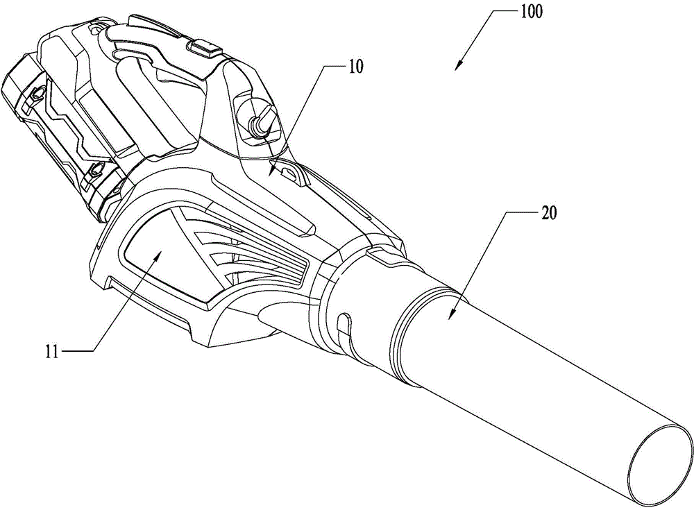
[0034] refer to Figures 1 to 6 As shown, the fan of the present invention is preferably a hair dryer 100 , which includes: a host 10 and an airflow guide assembly 20 .

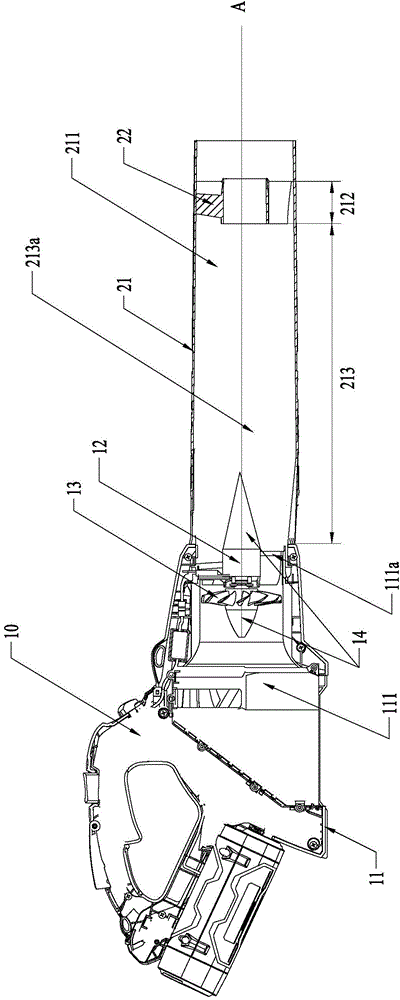
[0035] The host 10 includes: a casing 11 , a motor 12 and a fan 13 .

[0036] Wherein, the casing 11 includes: a host air duct 111 formed at least inside the host 10 and communicating with the outside. The motor 12 and the fan 13 are at least partly accommodated in the air duct of the main engine, and the motor 12 drives the fan 13 to rotate around the first axis A.

[0037] More specifically, the host air channel 111 is a through cavity formed by the shell 11 in the host 10, which at least includes an air channel interface 111a, and the motor 12 and the fan 13 are installed at the end of the through cavity as a whole after assembly. Or inside, when the fan 13 rotates, it...


PUM


Abstract

The invention provides a blower fan comprising a main machine which comprises an outer shell, a motor and a fan. The outer shell comprises a main machine air duct in which the motor and the fan are at least partially accommodated. The motor drives the fan to rotate with a first axis as the axis. The blower fan also comprises an air flow guide component which comprises an air drum used for guiding air flow, and a diversion member capable of guiding a part of air flow in the air drum to flow in other directions deviating from the first axis. The blower fan at least can serve as a dryer. With the diversion member, the blower fan can output combined air flow, and air flow, which deviates from the original guide direction, in the air flow disperses the counter-acting force brought by blowing, so that the feeling of fatigue of users during use is reduced and the operation feel is improved; air flow output at multiple angles improve the blowing effect, so that slice-shaped objects such as leaves can be blown easily.

Description

technical field [0001] The invention relates to a fan, in particular to a fan suitable for blowing. Background technique [0002] With the increasing development of hair dryers, people have higher requirements for the comfort and blowing effect of hair dryers; the previous hair dryers all blow out direct current air, because the airflow direction is single, so it will generate a large back thrust, now The wrist is pressed hard, making people uncomfortable to use; at the same time, due to the single airflow direction, it is easy to make the leaves stick to the ground and it is not easy to blow up, and the blowing effect is not good. Contents of the invention [0003] In order to solve the deficiencies of the prior art, the object of the present invention is to provide a fan capable of outputting composite airflow. [0004] In order to achieve the above object, the present invention adopts the following technical solutions: [0005] A fan, including: a host, the host inclu...

Claims


Application Information

Patent Timeline
IPC IPC(8): F04D25/08F04D29/54
Inventor 郭建朋聂方杰
Owner NANJING CHERVON IND
Why Eureka
Try Eureka