Check patentability & draft patents in minutes with Patsnap Eureka AI!

Gantry-type X-ray nondestructive detection device

A non-destructive testing and X-ray technology, applied in measuring devices, using radiation for material analysis, using wave/particle radiation for material analysis, etc., can solve the problem of unsteady up and down motion, low precision, inaccurate image acquisition, and noise of counterweights and other problems to achieve the effect of simple structure, reliable operation and noise avoidance

Active Publication Date: 2016-03-02
重庆凯立仪器有限公司
View PDF7 Cites 11 Cited by
  • Summary
  • Abstract
  • Description
  • Claims
  • Application Information

AI Technical Summary

Problems solved by technology

[0002] At present, the inspection equipment X-ray tube and the receiver in the X-ray non-destructive inspection device for large castings need to move up and down, left and right, and swing to cooperate with the functions of the forward and backward movement and rotation of the transport vehicle to collect the real-time data of the inspected workpiece and generate Dynamic images are used to judge the test results. The up and down movement of the detection equipment on the detection device is mostly driven by ordinary motors in the form of chains or synchronous belts. The unsteady up and down movement of this transmission mode has low precision, resulting in inaccurate image acquisition and poor imaging quality.
The sliding mechanism that moves up and down needs to add a counterweight to improve the stability of sliding, and the counterweight adopts a built-in type, and the counterweight is suspended in the inner cavity of the special-shaped tube in the column through the traction of the wire rope. Because the length of the column is limited, adding the counterweight in this way will be restricted, and at the same time, the weight slides and collides in the inner cavity of the special-shaped tube to generate noise

Method used


Image

  • Gantry-type X-ray nondestructive detection device
  • Gantry-type X-ray nondestructive detection device
  • Gantry-type X-ray nondestructive detection device

Examples


Embodiment Construction

[0031] The present invention will be further described below in conjunction with the accompanying drawings.

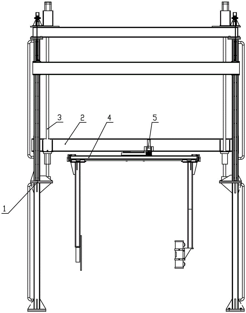
[0032] A gantry type X-ray non-destructive testing device, such as figure 1As shown, it consists of a gantry frame 1, a sliding beam mechanism 2, a sliding beam transmission mechanism 3, a C-arm mechanism 4 and a C-arm swing mechanism 5, wherein the sliding beam mechanism 2 and the sliding beam transmission mechanism 3 are installed on the gantry frame 1 Among them, the C-arm mechanism 4 and the C-arm swing mechanism 5 are installed in the sliding beam mechanism 2.

[0033] Gantry frame 1 as figure 2 As shown, it is composed of two lower vertical beams 6, two upper vertical beams 7 and a top beam 8, wherein the long rectangular lower vertical beam 6 is welded by a plurality of special-shaped steel pipes 9, as image 3 As shown, two handrails 10 are welded on the outside of the special-shaped steel pipe 9, and the upper and lower ends of the special-shaped steel pipe...


PUM


Abstract

The invention discloses a gantry-type X-ray nondestructive detection device which is composed of a gantry framework, a sliding beam mechanism, a sliding beam transmission mechanism, a C-shaped arm mechanism and a C-shaped arm swinging mechanism. The sliding beam mechanism and the sliding beam transmission mechanism are installed in the gantry framework, and the C-shaped arm mechanism and the C-shaped arm swinging mechanism are installed in the sliding beam mechanism. The detection device composed of all the mechanisms is matched with a workpiece transportation vehicle with a rotary tool to place a detection workpiece on a detection position, and the detection workpiece on the workpiece transportation vehicle can relatively move and rotate front and back relative to detection equipment on the detection device. The detection equipment on the detection device completes the functions of vertically moving, moving left and right and swinging relative to the detection workpiece, and therefore focusing and data collecting can be omni-directionally performed on different detection points of the workpiece, so that imaging is clear and X-ray nondestructive detection on large castings is completed. The gantry-type X-ray nondestructive detection device is simple in structure, reliable in operation, steady in transmission, high in precision and capable of preventing a balancing weight from sliding to generate noise and meeting the customer requirements.

Description

technical field [0001] The invention relates to an X-ray non-destructive testing device, in particular to a gantry type X-ray non-destructive testing device for testing large castings. Background technique [0002] At present, the inspection equipment X-ray tube and the receiver in the X-ray non-destructive inspection device for large castings need to move up and down, left and right, and swing to cooperate with the functions of the forward and backward movement and rotation of the transport vehicle to collect the real-time data of the inspected workpiece and generate Dynamic images are used to judge the detection results. The up and down movement of the detection equipment on the detection device is mostly driven by ordinary motors in the form of chains or synchronous belts. The unsteady up and down movement of this transmission method has low precision, resulting in inaccurate image acquisition and poor imaging quality. The sliding mechanism that moves up and down needs to...

Claims


Application Information

Patent Timeline
IPC IPC(8): G01N23/04
CPCG01N23/04G01N2223/3303
Inventor 付丹军宋伟王辉何宇
Owner 重庆凯立仪器有限公司
Features
  • R&D
  • Intellectual Property
  • Life Sciences
  • Materials
  • Tech Scout
  • Unparalleled Data Quality
  • Higher Quality Content
  • 60% Fewer Hallucinations
Learn More