Inserting tamping depth control device for cement concrete slump test

A cement concrete, depth control technology, applied in the direction of material inspection products, etc., can solve the problems affecting the test accuracy, difficult to control the insertion and tamping depth, etc., to achieve the effect of ensuring accuracy, simple structure, and convenient installation

Inactive Publication Date: 2016-03-02
HUBEI GEZHOUBA TESTING
View PDF0 Cites 5 Cited by
  • Summary
  • Abstract
  • Description
  • Claims
  • Application Information

AI Technical Summary

Problems solved by technology

According to the existing test equipment, it is difficult to control the depth of tamping when the upper two layers are inserted and tamped, which affects the test accuracy

Method used


Image

  • Inserting tamping depth control device for cement concrete slump test
  • Inserting tamping depth control device for cement concrete slump test
  • Inserting tamping depth control device for cement concrete slump test

Examples


Embodiment 1

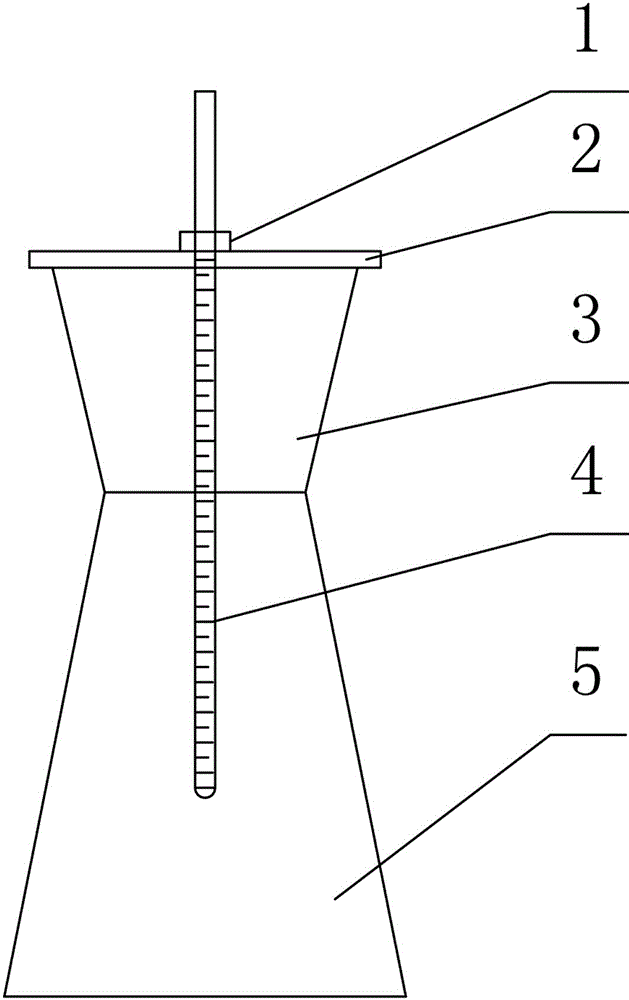
[0016] like Figure 1-3 As shown in , the cement concrete slump test inserts and tamps depth control device, the upper end of the tamping rod 4 with scale is covered with a positioning ring 1 that can move up and down along the tamping rod 4 with scale, and the lower end of the tamping rod 4 with scale passes through the charging funnel 3 The positioning hole on the top baffle plate 2 is inserted into the slump cylinder 5.

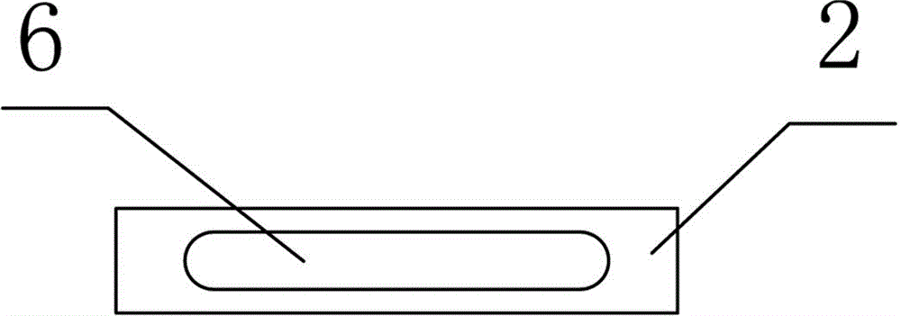
[0017] Preferably, the baffle 2 is a rectangular plate with a positioning hole 6 , and the length of the baffle 2 is greater than the diameter of the top surface of the charging funnel 3 .

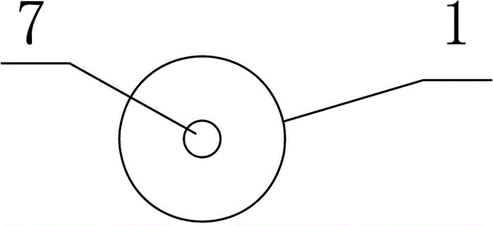
[0018] The locating ring 1 is a circular plate with a circular hole 7 , the circular hole 7 is in interference fit with the graduated tamper 4 , and the diameter of the locating ring 1 is larger than the width of the baffle plate 2 . The interference fit between the circular hole 7 and the tamping rod 4 with scale can make the positioning ring 1 be fixed on the desire...

Embodiment 2

[0024] The height of the slump cylinder 5 is 30cm, the height of the charging funnel 3 is 10cm, the thickness of the baffle plate 2 is 0.5cm, the height of the representative sample of the first layer of concrete in the slump cylinder 5 is 10cm, and the full length of the stamping rod 4 with scale is 60cm. And it is engraved with the scale line of 0 scale line at the top of the 4 hemispherical end of the stamping rod with scale, and the scale line of unit scale is 1mm. If it is necessary to penetrate through this layer and insert the lower layer to a depth of 2.5cm when inserting and pounding the second layer, the bottom surface of the positioning ring 1 should be fixed on the scale of the tamping rod 4 with a scale of 33cm (tube height 30+ funnel height 10+ baffle thickness 0.5 - The concrete sample height of the first layer is 10+, and it needs to be inserted into the lower layer at a depth of 2.5), so that when the second layer is penetrated, it can also be inserted into the...


PUM


Abstract

The invention discloses an inserting tamping depth control device for a cement concrete slump test. The upper end of a tamping rod with scales is sleeved with a positioning ring which can vertically move along the tamping rod with the scales, and the lower end of the tamping rod with the scales penetrates through a positioning hole formed in a baffle arranged on the top surface of a feeding hopper, so that the lower end of the tamping rod with the scales is inserted into a slump barrel. According to the inserting tamping depth control device for the cement concrete slump test, the upper end of the tamping rod with the scales is sleeved with the positioning ring which can vertically move along the tamping rod with the scales, the positioning ring is fixed at the portion, with the corresponding scale, of the tamping rod with the scales according to the needed inserting depth, and the lower end of the tamping rod with the scales penetrates through the positioning hole formed in the baffle arranged on the top surface of the feeding hopper, so that the tamping rod with the scales is inserted into a slump barrel to perform precise inserting tamping. The inserting tamping depth control device for the cement concrete slump test is simple in structure, convenient to install and precise in inserting tamping depth, and therefore the accuracy of a test result is guaranteed.

Description

technical field [0001] The invention relates to a cement concrete slump test auxiliary device, in particular to a cement concrete slump test insertion and tamping depth control device. Background technique [0002] In highway construction, the cement concrete slump test is the most commonly used test method to detect the consistency of concrete mixture. During the test, representative samples need to be loaded into the cylinder in three layers, and the height of each layer is slightly greater than one-third of the height of the cylinder. One, use a tamping stick to evenly insert and tamp 25 times on the cross-section of each layer. Inserting and tamping is carried out on the entire area, from the edge to the center along the spiral line. When inserting and tamping the bottom layer, insert it to the bottom layer. When inserting and tamping the other two layers, it should penetrate through this layer and insert about 20mm to 30mm into the lower layer. The insertion and tamping...

Claims


Application Information

Patent Timeline
Patent Type & Authority Applications(China)
IPC IPC(8): G01N33/38
Inventor 方俊杰宁全纪
Owner HUBEI GEZHOUBA TESTING
Why Eureka
Try Eureka