Charging plug locking device

A charging plug and locking device technology, applied in the field of locking devices, can solve problems such as damage to the charging plug, interruption of charging, etc., and achieve the effects of simple structure, convenient use, and easy removal.

Inactive Publication Date: 2016-03-02
ZHANGJIAGANG UCHEN NEW ENERGY TECH CO LTD
View PDF5 Cites 13 Cited by
  • Summary
  • Abstract
  • Description
  • Claims
  • Application Information

AI Technical Summary

Problems solved by technology

But because the rear part of the hook is relatively close to the handle, when charging, it often touches the rear part of the hook due to improper operation, so that the charging stand and the charging plug will be disengaged, which will not only cause the interruption of charging, but also easily cause the Damaged charging plug

Method used


Image

  • Charging plug locking device
  • Charging plug locking device

Examples


Embodiment Construction

[0011] The locking device of the charging plug according to the present invention will be further described in detail through specific embodiments below.

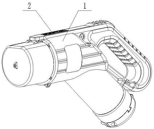
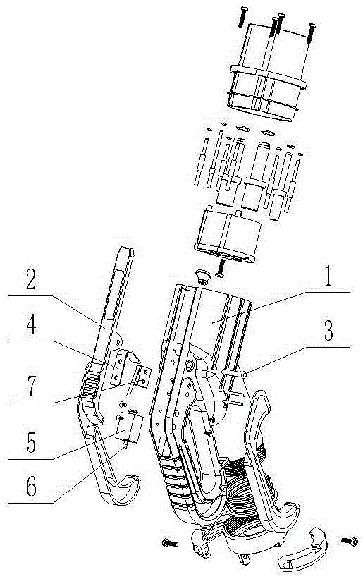
[0012] Such as figure 1 , figure 2 As shown, the locking device of the charging plug includes a charging plug. A hook 2 is hinged on the housing 1 of the charging plug. The front end of the hook 2 is hook-shaped. The housing 1 of the charging plug is hinged, the housing 1 of the charging plug is provided with an electromagnet 5, the electromagnet 5 is provided with a movable rod 6, and the hook 2 is provided with a locking hole that matches the movable rod 6. When the electromagnetic Movable bar 6 stretches out when iron 5 is energized, and inserts in the locking hole. The housing 1 of the charging plug is also provided with a micro switch 7, the touch rod of the micro switch 7 conflicts with the hook 2, and when the rear part of the hook 2 is pressed, the micro switch 7 is turned on.

[0013] The working principle of t...


PUM


Abstract

The invention relates to a charging plug locking device. The charging plug locking device comprises a charging plug; a clamping hook is hinged with the shell of the charging plug; the front end of the clamping hook is shaped as a hook; the middle part of the clamping hook is hinged with the shell of the charging plug; an electromagnet is arranged in the shell of the charging plug; a movable bar is arranged in the electromagnet; a locking hole matched with the movable bar is arranged in the clamping hook; and, when the electromagnet is electrified, the movable bar extends out and is inserted into the locking hole. The charging plug locking device disclosed by the invention is simple in structure and convenient to use; the clamping hook is locked while charging is carried out in the form of the electromagnet; the problems that charging is interrupted or the charging plug is damaged due to improper operations can be avoided; furthermore, the clamping hook is automatically unlocked after power is off; and then, the charging plug can be conveniently taken down.

Description

technical field [0001] The invention relates to a locking device for a charging plug. Background technique [0002] When the electric vehicle is being charged, the charging plug needs to be docked with the charging stand, and the hook on the charging plug needs to be engaged to prevent the charging stand from being released from the charging plug. Currently used charging plugs usually use pins and torsion springs for their hooks, that is, pins and torsion springs are set in the middle of the hook, and when the rear part of the hook is pressed, the front part of the hook will be lifted. After the charging stand is hooked, the torsion force of the torsion spring realizes the automatic reset of the hook after being pressed. But because the rear part of the hook is relatively close to the handle, when charging, it often touches the rear part of the hook due to improper operation, so that the charging stand and the charging plug will be disengaged, which will not only cause the ...

Claims


Application Information

Patent Timeline
Patent Type & Authority Applications(China)
IPC IPC(8): H01R13/639H01R13/66H01R13/70B60L11/18
CPCB60L53/16H01R13/639H01R13/6608H01R13/70H01R2201/26Y02T10/70Y02T10/7072Y02T90/14
Inventor 陈建刚
Owner ZHANGJIAGANG UCHEN NEW ENERGY TECH CO LTD
Why Eureka
Try Eureka