
Terminal-equipped wire and method of producing terminal-equipped wire

一种端子、电线的技术,应用在电路、导电材料、导电材料等方向,能够解决电蚀等问题,达到提高耐电蚀性的效果

Active Publication Date: 2016-03-02
AUTONETWORKS TECH LTD +3
View PDF9 Cites 4 Cited by
  • Summary
  • Abstract
  • Description
  • Claims
  • Application Information

AI Technical Summary

Problems solved by technology

Therefore, if water adheres to the connection portion where the terminal and the core wire are connected to each other, there is a concern that a so-called corrosion current flows between the terminal, the core wire, and the water to cause galvanic corrosion

Method used


Image

  • Terminal-equipped wire and method of producing terminal-equipped wire
  • Terminal-equipped wire and method of producing terminal-equipped wire
  • Terminal-equipped wire and method of producing terminal-equipped wire

Examples


Embodiment approach 1

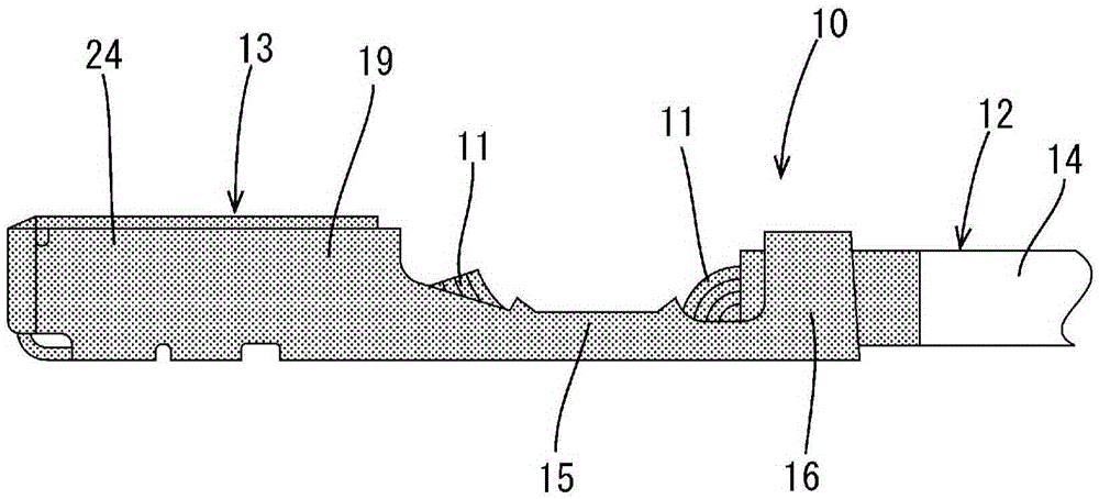
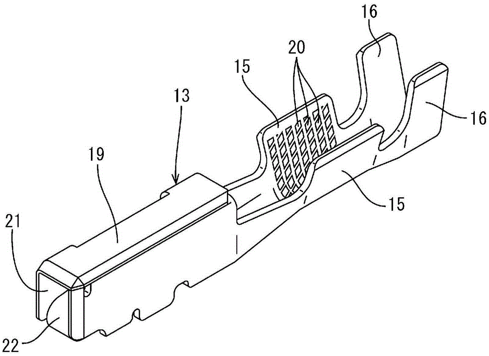
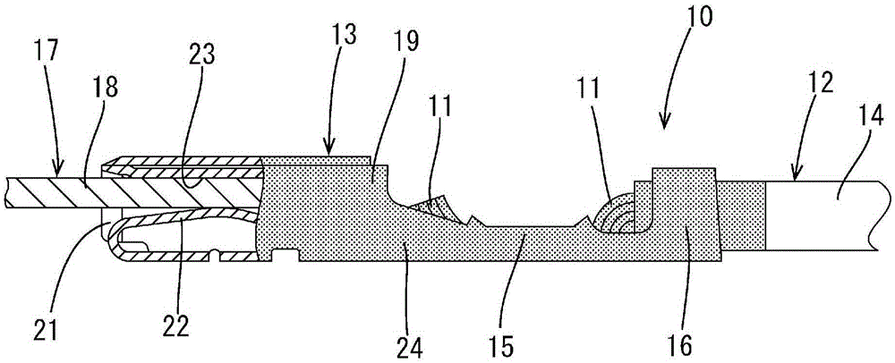
[0051] will refer to Figure 1-7 Embodiment 1 of the present invention will be described. The electric wire 10 with a terminal according to the present embodiment includes an electric wire 12 containing a core wire 11 containing a metal having a higher ionization tendency than copper and a terminal 13 containing copper or a copper alloy. It should be noted that in the following description, the figure 1 The left side of is called "front" and the right side is called "back".

[0052] wire 12

[0053]The electric wire 12 is obtained by surrounding the outer periphery of the core wire 11 with an insulating coating 14 made of synthetic resin. A metal having a higher ionization tendency than copper can be used as the metal constituting the core wire 11, and examples thereof include magnesium, aluminum, manganese, zinc, chromium, iron, cadmium, cobalt, nickel, tin, and lead, or alloys thereof . In this embodiment, the core wire 11 contains aluminum or an aluminum alloy. The c...

Embodiment approach 2

[0121] Next, we will refer to Figure 8 Embodiment 2 of the present invention will be described. The electric wire 40 with a terminal according to the present embodiment includes: a plurality of (two in the present embodiment) electric wires 42 each including a core wire 41 made of a metal member including an ionized Aluminum or an aluminum alloy which tends to be larger than copper; and a spliced ​​terminal 43 (an example of the terminal 13 ) which contains copper or a copper alloy and is connected to a plurality of core wires exposed from the end of the electric wire 42 41. It should be noted that repeated descriptions in Embodiment Mode 1 are omitted.

[0122] In the present embodiment, the splicing terminal 43 includes a wire barrel portion 44 crimped to both of the two core wires 41 so as to wind the core wires 41 .

[0123] A plating layer (not shown) made of a metal for plating whose ionization tendency is closer to copper than to aluminum may be formed on the surfac...


PUM


Abstract

A terminal-equipped wire (10) is provided with the following: a wire (12) which is provided with a core wire (11) comprising metal of a greater ionization tendency than copper, the core wire (11) being exposed from an end; and a terminal (13) that comprises copper or copper alloy and is connected to the exposed core wire (11). Formed on the surface of the terminal (13) is a surface treatment layer (24) comprising a surface treatment agent (26) that forms a liquid or a paste and has a molecular structure including an affinity group having affinity to the terminal (13) and a hydrophobic group having hydrophobicity. Due to this configuration, the electrolytic corrosion resistance of the terminal-equipped wire (10) is improved.

Description

technical field [0001] The present invention relates to a technique for a terminated electric wire in which a terminal is connected to an end of the electric wire. Background technique [0002] Conventionally, an electric wire with a terminal (ie, an electric wire provided with a terminal) including an electric wire including a core wire and a terminal connected to the core wire exposed from the end of the electric wire is known. Recently, in order to reduce the weight of electric wires, attempts have been made to use core wires containing aluminum or an aluminum alloy. [0003] Typically, the terminals are constructed of copper or copper alloys with high electrical conductivity. Therefore, if water adheres to the connection portion where the terminal and the core wire are connected to each other, there is a concern that so-called corrosion current flows between the terminal, the core wire, and the water to cause galvanic corrosion. [0004] In view of the above circumstan...

Claims


Application Information

Patent Timeline
Patent Type & Authority Applications(China)
IPC IPC(8): H01R4/18H01R4/62
CPCH01R4/62H01R4/185H01R4/188H01R13/03H01B1/023H01R4/18H01R13/533H01R43/048
Inventor 野村秀树平井宏树小野纯一大塚拓次细川武广长谷达也后藤和宏中岛一雄沟口诚
Owner AUTONETWORKS TECH LTD
Learn More