
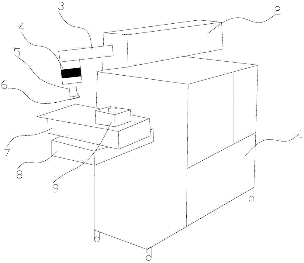
Small laser welding machine structure

A technology of laser welding machine and laser welding head, which is applied in the direction of laser welding equipment, welding equipment, metal processing equipment, etc., can solve the problems of increased production costs and achieve the effect of increasing the welding range

Inactive Publication Date: 2016-03-09
SUZHOU RECEN PRECISION MACHINERY CO LTD
View PDF15 Cites 2 Cited by
  • Summary
  • Abstract
  • Description
  • Claims
  • Application Information

AI Technical Summary

Problems solved by technology

However, in actual use, sometimes there are some large-sized workpieces that need to be welded. This small laser welding machine is difficult to meet the requirements, but if a large laser welding machine is purchased, the production cost of the enterprise will increase. Therefore, it is necessary to design a small laser welding machine that can meet the welding requirements of larger workpieces.

Method used


Image

  • Small laser welding machine structure

Examples


Embodiment Construction

[0013] The implementation of the present invention will be illustrated by specific specific examples below, and those skilled in the art can easily understand other advantages and effects of the present invention from the contents disclosed in this specification.

[0014] see figure 1 . It should be noted that the structures, proportions, sizes, etc. shown in the drawings attached to this specification are only used to match the content disclosed in the specification, for those who are familiar with this technology to understand and read, and are not used to limit the implementation of the present invention. Limiting conditions, so there is no technical substantive meaning, any modification of structure, change of proportional relationship or adjustment of size, without affecting the effect and purpose of the present invention, should still fall within the scope of the present invention. The disclosed technical content must be within the scope covered. At the same time, term...


PUM


Abstract

The invention provides a small laser welding machine structure. A laser welding head of the small laser welding machine structure is connected with a driving air cylinder, and a laser focusing lens is connected with the laser welding head. According to a small laser welding machine, the welding head is connected with the driving air cylinder, and the driving air cylinder is a rotating air cylinder; in other words, the welding head can reciprocate in the longitudinal direction and can also swing back and forth in the left-and-right direction; in this way, when a workpiece is welded, the welding head is matched with a longitudinal moving sliding table and a transverse moving sliding table below a working table to move in the opposite directions, the welding range of the welding head can be effectively expanded accordingly, and some workpieces with large sizes can be welded on the small laser welding machine accordingly.

Description

technical field [0001] The invention relates to the field of laser welding, in particular to a structure of a small laser welding machine. Background technique [0002] Laser welding machine, also often called laser welding machine and laser welding machine, is a machine for laser material processing. According to its working mode, it can be divided into laser mold welding machine, automatic laser welding machine, laser spot welding machine, and optical fiber transmission laser welding machine. Machine and optical welding is to use high-energy laser pulses to locally heat materials in a small area. The energy of laser radiation diffuses to the inside of materials through heat conduction, and the materials are melted to form a specific molten pool to achieve the purpose of welding. Laser welding is the use of high-energy laser pulses to locally heat materials in a small area. The energy of laser radiation diffuses into the interior of the material through heat conduction, and...

Claims


Application Information

Patent Timeline
Patent Type & Authority Applications(China)
IPC IPC(8): B23K26/21B23K26/08
CPCB23K26/20B23K26/0853B23K26/0876
Inventor 程振峰
Owner SUZHOU RECEN PRECISION MACHINERY CO LTD
Learn More